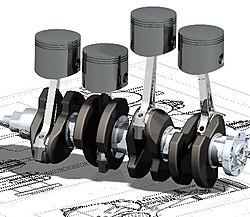
The crankshaft is located within the engine block and held in place via main bearings which allow the crankshaft to rotate within the block.[4] The up-down motion of each piston is transferred to the crankshaft via connecting rods.[5] A flywheel is often attached to one end of the crankshaft, in order to smoothen the power delivery and reduce vibration.[6]
A crankshaft is subjected to enormous stresses, in some cases more than 8.6 tonnes (19,000 pounds) per cylinder.[7] Crankshafts for single-cylinder engines are usually a simpler design than for engines with multiple cylinders.
The crankshaft is able to rotate in the engine block due to the 'main bearings'. Since the crankshaft is subject to large horizontal and torsional forces from each cylinder, these main bearings are located at various points along the crankshaft, rather than just one at each end.[8] The number of main bearings is determined based on the overall load factor and the maximum engine speed. Crankshafts in diesel engines often use a main bearing between every cylinder and at both ends of the crankshaft, due to the high forces of combustion present.[9]
Flexing of the crankshaft was a factor in replacing straight-eight engines in the 1950s; the long crankshafts suffered from an unacceptable amount of flex when engine designers began using higher compression ratios and higher engine speeds (RPM).[10]
Piston stroke
The distance between the axis of the crankpins and the axis of the crankshaft determines the stroke length of the engine.[1]
Most modern car engines are classified as "over square" or short-stroke,[citation needed] wherein the stroke is less than the diameter of the cylinder bore. A common way to increase the low-RPM torque of an engine is to increase the stroke, sometimes known as "stroking" the engine. Historically, the trade-off for a long-stroke engine was a lower rev limit and increased vibration at high RPM, due to the increased piston velocity.[11]
Cross-plane and flat-plane configurations
When designing an engine, the crankshaft configuration is closely related to the engine's firing order.[12][13]
Most production V8 engines (such as the Ford Modular engine and the General Motors LS engine) use a cross-plane crank whereby the crank throws are spaced 90 degrees apart.[14] However, some high-performance V8 engines (such as the Ferrari 488)[15][16] instead use a flat-plane crank, whereby the throws are spaced 180° apart, which essentially results in two inline-four engines sharing a common crankcase. Flat-plane engines are usually able to operate at higher RPM, however they have higher second-order vibrations,[17] so they are better suited to racing car engines.[18]
Engine balance
For some engines it is necessary to provide counterweights for the reciprocating mass of the piston, conrods and crankshaft, in order to improve the engine balance.[19][20] These counterweights are typically cast as part of the crankshaft but, occasionally, are bolt-on pieces.[citation needed]
Flying arms
Flying arm (the boomerang-shaped link between first and second crankpins on a crankshaft)
In some engines, the crankshaft contains direct links between adjacent crankpins, without the usual intermediate main bearing. These links are called flying arms.[21]:16,41 This arrangement is sometimes used in V6 and V8 engines, in order to maintain an even firing interval while using different V angles, and to reduce the number of main bearings required. The downside of flying arms is that the rigidity of the crankshaft is reduced, which can cause problems at high RPM or high power outputs.[22]
Counter-rotating crankshafts
In most engines, each connecting rod is attached to a single crankshaft, which results in the angle of the connecting rod varying as the piston moves through its stroke. This variation in angle pushes the pistons against the cylinder wall, which causes friction between the piston and cylinder wall.[23] To prevent this, some early engines – such as the 1900–1904 Lanchester Engine Company flat-twin engines – connected each piston to two crankshafts that rotated in opposite directions. This arrangement cancels out the lateral forces and reduces the requirement for counterweights. This design is rarely used; however a similar principle applies to balance shafts, which are occasionally used.
Eccentricity and dynamic displacement of diesel engines
Eccentricity and dynamic displacement are critical factors influencing the performance, efficiency, and durability of diesel engines. These phenomena arise due to the flexibility of the crankshaft, secondary piston motion, and varying loads during engine operation. Understanding these effects is essential for reducing mechanical wear, improving fuel efficiency, and optimizing engine design.[24]
Crankshafts can be created from a steel bar using roll forging. Today, manufacturers tend to favour the use of forged crankshafts due to their lighter weight, more compact dimensions and better inherent damping.[25] With forged crankshafts, vanadium micro-alloyed steels are mainly used as these steels can be air-cooled after reaching high strengths without additional heat treatment, except for the surface hardening of the bearing surfaces. The low alloy content also makes the material cheaper than high-alloy steels. Carbon steels also require additional heat treatment to reach the desired properties.
Cast crankshafts
Another construction method is to cast the crankshaft from ductile iron. Cast iron crankshafts are today mostly found in cheaper production engines where the loads are lower.[26]
Machined crankshafts
Crankshafts can also be machined from billet, often a bar of high quality vacuum remelted steel. Though the fiber flow (local inhomogeneities of the material's chemical composition generated during casting) does not follow the shape of the crankshaft (which is undesirable), this is usually not a problem since higher quality steels, which normally are difficult to forge, can be used. Per unit, these crankshafts tend to be expensive due to the large amount of material that must be removed with lathes and milling machines, the high material cost, and the additional heat treatment required. However, since no expensive tooling is needed, this production method allows small production runs without high up-front costs.[27]
History
Crankshaft
In 9th century AbbasidBaghdad, automatically operated cranks appear in several of the hydraulic devices described by the Banū Mūsā brothers in the Book of Ingenious Devices.[28] These automatically operated cranks appear in several devices, two of which contain an action which approximates to that of a crankshaft, five centuries before the earliest known European description of a crankshaft. However, the automatic crank mechanism described by the Banū Mūsā would not have allowed a full rotation, but only a small modification was required to convert it to a crankshaft.[29]
In the Artuqid Sultanate, Arab engineer Ismail al-Jazari (1136–1206) described a crank and connecting rod system in a rotating machine for two of his water-raising machines,[30] which include both crank and shaft mechanisms.[31]
15th century paddle-wheel boat
The Italian physician Guido da Vigevano (c.1280– c.1349), planning for a new Crusade, made illustrations for a paddle boat and war carriages that were propelled by manually turned compound cranks and gear wheels,[32] identified as an early crankshaft prototype by Lynn Townsend White.[33]
Crankshafts were described by Leonardo da Vinci (1452–1519)[30] and a Dutch farmer and windmill owner by the name Cornelis Corneliszoon van Uitgeest in 1592. His wind-powered sawmill used a crankshaft to convert a windmill's circular motion into a back-and-forward motion powering the saw. Corneliszoon was granted a patent for his crankshaft in 1597.
From the 16th century onwards, evidence of cranks and connecting rods integrated into machine design becomes abundant in the technological treatises of the period: Agostino Ramelli's The Diverse and Artifactitious Machines of 1588 depicts eighteen examples, a number that rises in the Theatrum Machinarum Novum by Georg Andreas Böckler to 45 different machines.[34] Cranks were formerly common on some machines in the early 20th century; for example almost all phonographs before the 1930s were powered by clockwork motors wound with cranks. Reciprocating piston engines use cranks to convert the linear piston motion into rotational motion. Internal combustion engines of early 20th century automobiles were usually started with hand cranks, before electric starters came into general use.
See also
Wikimedia Commons has media related to Crankshaft .
↑Andersson B S (3–6 September 1991), "Company's perspective in vehicle tribology", in Dowson, D; Taylor, C M; Godet, M (eds.), 18th Leeds-Lyon Symposium, New York: Elsevier, pp.503–506
↑A. F. L. Beeston, M. J. L. Young, J. D. Latham, Robert Bertram Serjeant (1990), The Cambridge History of Arabic Literature, Cambridge University Press, p.266, ISBN0-521-32763-6{{citation}}: CS1 maint: multiple names: authors list (link)
Hägermann, Dieter; Schneider, Helmuth (1997), Propyläen Technikgeschichte. Landbau und Handwerk, 750 v. Chr. bis 1000 n. Chr. (2nded.), Berlin, ISBN3-549-05632-X{{citation}}: CS1 maint: location missing publisher (link)
Hall, Bert S. (1979), The Technological Illustrations of the So-Called "Anonymous of the Hussite Wars". Codex Latinus Monacensis 197, Part 1, Wiesbaden: Dr. Ludwig Reichert Verlag, ISBN3-920153-93-6
Laur-Belart, Rudolf (1988), Führer durch Augusta Raurica (5thed.), Augst{{citation}}: CS1 maint: location missing publisher (link)
Lucas, Adam Robert (2005), "Industrial Milling in the Ancient and Medieval Worlds. A Survey of the Evidence for an Industrial Revolution in Medieval Europe", Technology and Culture, 46 (1): 1–30, doi:10.1353/tech.2005.0026, S2CID109564224
Mangartz, Fritz (2006), "Zur Rekonstruktion der wassergetriebenen byzantinischen Steinsägemaschine von Ephesos, Türkei. Vorbericht", Archäologisches Korrespondenzblatt, 36 (1): 573–590
Mangartz, Fritz (2010), Die byzantinische Steinsäge von Ephesos. Baubefund, Rekonstruktion, Architekturteile, Monographs of the RGZM, vol.86, Mainz: Römisch-Germanisches Zentralmuseum, ISBN978-3-88467-149-8
Needham, Joseph (1986), Science and Civilisation in China: Volume 4, Physics and Physical Technology: Part 2, Mechanical Engineering, Cambridge University Press, ISBN0-521-05803-1
Nunney, Malcolm J. (2007), Light and Heavy Vehicle Technology (4thed.), Elsevier Butterworth-Heinemann, ISBN978-0-7506-8037-0
Ritti, Tullia; Grewe, Klaus; Kessener, Paul (2007), "A Relief of a Water-powered Stone Saw Mill on a Sarcophagus at Hierapolis and its Implications", Journal of Roman Archaeology, 20: 138–163, doi:10.1017/S1047759400005341, S2CID161937987
Schiöler, Thorkild (2009), "Die Kurbelwelle von Augst und die römische Steinsägemühle", Helvetia Archaeologica, vol.40, no.159/160, pp.113–124
Volpert, Hans-Peter (1997), "Eine römische Kurbelmühle aus Aschheim, Lkr. München", Bericht der Bayerischen Bodendenkmalpflege, 38: 193–199, ISBN3-7749-2903-3
White, Lynn Jr. (1962), Medieval Technology and Social Change, Oxford: At the Clarendon Press
Grewe, Klaus (2009). "Die Reliefdarstellung einer antiken Steinsägemaschine aus Hierapolis in Phrygien und ihre Bedeutung für die Technikgeschichte. Internationale Konferenz 13.−16. Juni 2007 in Istanbul". In Bachmann, Martin (ed.). Bautechnik im antiken und vorantiken Kleinasien(PDF). Byzas (in German). Vol.9. Istanbul: Ege Yayınları/Zero Prod. Ltd. pp.429–454. ISBN978-975-807-223-1. Archived from the original(PDF) on 2011-05-11.
This page is based on this Wikipedia article Text is available under the CC BY-SA 4.0 license; additional terms may apply. Images, videos and audio are available under their respective licenses.