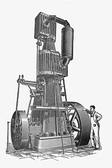
A steeple compound engine is a form of tandem compound steam engine that is constructed as an inverted vertical engine. Because of their great height, they became known as "steeple" engines.
A steeple compound engine is a form of tandem compound steam engine that is constructed as an inverted vertical engine. Because of their great height, they became known as "steeple" engines.
Compound engines have either two or three cylinders, in which the steam is expanded in turn. The exhaust of the high-pressure or HP cylinder feeds the low-pressure or LP cylinder. Three cylinder engines also had an intermediate-pressure or IP cylinder, but these were less common than two cylinder engines. [lower-roman 1] . In the tandem compound the cylinders are arranged end to end on a common axis (in this case, vertical) with both pistons mounted on the same rod and moving together. Each cylinder has independent valves and valve gear. The pipe connecting them may be enlarged to form a 'receiver', a reservoir for steam at the intermediate pressure. This improves the efficiency of compound engines. [2]
Other than their great height, the tandem compound steeple engine had no connection to Napier's earlier steeple engine, as used for paddle steamers on the Clyde. [3] The vertical tandem compound has been used for marine use in small steamboats, although not under the 'steeple' name. [4] Horizontal space in such boats is often more restricted than vertical space.
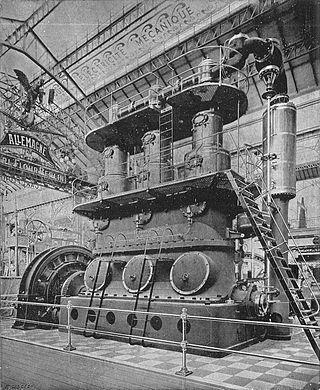
The Fitchburg engine (illus.) [lower-roman 2] was one of a series of similar engines offered in various configurations. The steeple arrangement required a high ceiling to the engine house, but had two advantages: [6] it took up less floor space than a horizontal engine and it also required less complex masonry foundations beneath the engine. A vertical engine could be erected on any reasonably level base that was strong enough to bear its weight. A horizontal engine required carefully aligned brickwork to support both the crankshaft and cylinder(s) separately. Such brickwork was costly, took time to build and also prevented new engines being installed in old engine houses without expensive rebuilding.
Fitchburg were notable in also supplying an automatic governor (illus., left-hand flywheel) that controlled the valve's cut-off according to load. Such governors would become significant around 1900 with the development of the high-speed engine, where they were used to control speed precisely. In these earlier medium-speed engines, the function of these governors was not just to control the engine's speed, but also to improve efficiency. [7] The Fitchburg piston valves could be operated with a cut-off from zero to two-thirds of the stroke. A shorter cut-off improves efficiency when operating under light loads. Earlier engines had used devices such as expansion valves to achieve this, but they also required the continued attention of a skilled driver, who could 'drive' the engine by varying the cut-off as load changed. The earlier Watt governors only controlled a throttle valve, so although they controlled an engine's speed, they did not encourage efficiency. An engine operating with no cut-off but a throttled steam supply will be operating inefficiently, owing to reduced expansive working and the risk of wire-drawing. The first 'automatic' governors were termed that because they not only controlled the speed, but could also take over the role of the driver and could vary cut-off too. [8] [9]

One of the best-known examples of the steeple engine was the Willans engine. [10] These were double- or triple-expansion compound engines, with the unusual features of single-acting cylinders and a central spindle valve shared between all cylinders. [11] [12] By around 1900, more of the Willans type were in service for electrical generation than any other type. [9]
One of the last steeple compound engine designs was the Skinner Unaflow of 1929. Although some were used as stationary engines and generator sets, most were marine engines. The Great Lakes ferry SS Badger continues in service with her original engines. [13]

A steam engine is a heat engine that performs mechanical work using steam as its working fluid. The steam engine uses the force produced by steam pressure to push a piston back and forth inside a cylinder. This pushing force can be transformed, by a connecting rod and crank, into rotational force for work. The term "steam engine" is generally applied only to reciprocating engines as just described, not to the steam turbine. Steam engines are external combustion engines, where the working fluid is separated from the combustion products. The ideal thermodynamic cycle used to analyze this process is called the Rankine cycle. In general usage, the term steam engine can refer to either complete steam plants, such as railway steam locomotives and portable engines, or may refer to the piston or turbine machinery alone, as in the beam engine and stationary steam engine.

The valve gear of a steam engine is the mechanism that operates the inlet and exhaust valves to admit steam into the cylinder and allow exhaust steam to escape, respectively, at the correct points in the cycle. It can also serve as a reversing gear. It is sometimes referred to as the "motion".
Steam power developed slowly over a period of several hundred years, progressing through expensive and fairly limited devices in the early 17th century, to useful pumps for mining in 1700, and then to Watt's improved steam engine designs in the late 18th century. It is these later designs, introduced just when the need for practical power was growing due to the Industrial Revolution, that truly made steam power commonplace.
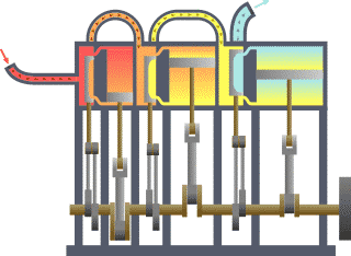
A compound steam engine unit is a type of steam engine where steam is expanded in two or more stages. A typical arrangement for a compound engine is that the steam is first expanded in a high-pressure (HP) cylinder, then having given up heat and losing pressure, it exhausts directly into one or more larger-volume low-pressure (LP) cylinders. Multiple-expansion engines employ additional cylinders, of progressively lower pressure, to extract further energy from the steam.

The Walschaerts valve gear is a type of valve gear used to regulate the flow of steam to the pistons in steam locomotives, invented by Belgian railway engineer Egide Walschaerts in 1844. The gear is sometimes named without the final "s", since it was incorrectly patented under that name. It was extensively used in steam locomotives from the late 19th century until the end of the steam era.
In a steam engine, cutoff is the point in the piston stroke at which the inlet valve is closed. On a steam locomotive, the cutoff is controlled by the reversing gear.

A Corliss steam engine is a steam engine, fitted with rotary valves and with variable valve timing patented in 1849, invented by and named after the American engineer George Henry Corliss of Providence, Rhode Island.
Engine efficiency of thermal engines is the relationship between the total energy contained in the fuel, and the amount of energy used to perform useful work. There are two classifications of thermal engines-
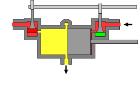
The uniflow type of steam engine uses steam that flows in one direction only in each half of the cylinder. Thermal efficiency is increased by having a temperature gradient along the cylinder. Steam always enters at the hot ends of the cylinder and exhausts through ports at the cooler centre. By this means, the relative heating and cooling of the cylinder walls is reduced.
A compound locomotive is a steam locomotive which is powered by a compound engine, a type of steam engine where steam is expanded in two or more stages. The locomotive was only one application of compounding. Two and three stages were used in ships, for example.

An expansion valve is a device in steam engine valve gear that improves engine efficiency. It operates by closing off the supply of steam early, before the piston has travelled through its full stroke. This cut-off allows the steam to then expand within the cylinder. This expanding steam is still sufficient to drive the piston, even though its pressure decreases as it expands. As less steam is supplied in the shorter time for which the valve is open, use of the expansion valve reduces the steam consumed and thus the fuel required. The engine may deliver two-thirds of the work, for only one-third of the steam.

A marine steam engine is a steam engine that is used to power a ship or boat. This article deals mainly with marine steam engines of the reciprocating type, which were in use from the inception of the steamboat in the early 19th century to their last years of large-scale manufacture during World War II. Reciprocating steam engines were progressively replaced in marine applications during the 20th century by steam turbines and marine diesel engines.

The Stirling boiler is an early form of water-tube boiler, used to generate steam in large land-based stationary plants. Although widely used around 1900, it has now fallen from favour and is rarely seen.
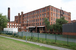
George Saxon & Co was an English engineering company that manufactured stationary steam engines. It was based in the Openshaw district of Manchester. The company produced large steam-driven engines for power stations and later for textile mills in Lancashire and elsewhere.
The South African Railways Class MA 2-6-6-0 of 1909 was a steam locomotive from the pre-Union era in the Natal Colony.

A return connecting rod, return piston rod or double piston rod engine or back-acting engine is a particular layout for a steam engine.
High-speed steam engines were one of the final developments of the stationary steam engine. They ran at a high speed, of several hundred rpm, which was needed by tasks such as electricity generation.
A bash valve is a valve within a piston engine, used to control the admission of the working fluid. They are directly actuated valves, operated by contact between the piston and the valve tip.
The Willans engine or central valve engine was a high-speed stationary steam engine used mainly for electricity generation around the start of the 20th century.