Expansion valve (steam engine)

Last updated
Cross compound engine, with an expansion valve (top) on the high-pressure cylinder Cross compound engine, plan section (Heat Engines, 1913).jpg
Cross compound engine, with an expansion valve (top) on the high-pressure cylinder

An expansion valve is a device in steam engine valve gear that improves engine efficiency. It operates by closing off the supply of steam early, before the piston has travelled through its full stroke. This cut-off allows the steam to then expand within the cylinder. [1] This expanding steam is still sufficient to drive the piston, even though its pressure decreases as it expands. [lower-roman 1] As less steam is supplied in the shorter time for which the valve is open, use of the expansion valve reduces the steam consumed and thus the fuel required. [2] The engine (on 1875 figures) may deliver two-thirds of the work, for only one-third of the steam. [2]

Contents

Indicator diagram showing steam pressure with piston movement Indicator diagram steam admission.svg
Indicator diagram showing steam pressure with piston movement

An expansion valve is a secondary valve within a steam engine. They represent an intermediate step between steam engines with non-expansive working and later valve gears that could provide for expansion by controlling the motion of a single valve.

Expansion valves were used for stationary engines and marine engines. [1] They were not used for locomotives, although expansive working was achieved by the use of the later variable expansion valve gears.

Need for varying expansion

The pressure of the expanded steam is less than that of steam supplied directly from the boiler. An engine working with an expansion valve set to an early cut-off is thus less powerful than with the valve fully open. Accordingly, the engine must now be driven, so that the valve is manually adjusted as the load on the engine changes. An engine running under light load may be operated efficiently with an early cut-off, an engine under heavy load may require a longer cut-off and the cost of more steam consumption.

When Trevithick supplied his 1801 engine [lower-roman 2] for a rolling mill at Tredegar Iron Works, [3] the engine was more powerful when worked without expansion and Samuel Homfray, the ironmaster, preferred to use the extra power despite the potential saving in coal costs [4]

Gridiron expansion valves

Independent gridiron valve, with conventional slide valve Expansion valve (Steam and the Steam Engine, Evers).jpg
Independent gridiron valve, with conventional slide valve
Eccentric and varying ratio linkage to drive a gridiron expansion valve Working of Expansion Valve (Steam and the Steam Engine, Evers).jpg
Eccentric and varying ratio linkage to drive a gridiron expansion valve

The gridiron valve [5] was one of the first forms of expansion valve. [1] The gridiron valve is an arrangement of two plates with overlapping slats. One plate can move so that its slats overlap either the slats of the other plate, or the slots between them, to thus be either open or closed. It has the advantages of a relatively large opening (up to half of the total area) and a rapid opening, needing to be moved by only one slat width to change from fully open to fully closed. Its disadvantage is that they do not seal particularly well. Because of the short actuating distance for a gridiron valve their valve timing would be relatively imprecise if used with an eccentric or similar. Some large steam engines later used them as primary valves, either as exhaust valves for LP cylinders [6] or as inlet valves in conjunction with trip- [7] or cam valve gear. [8] [lower-roman 3]

Where gridiron valves are used as secondary valves, they were commonly mounted on the inlet side of the valve chamber for the primary slide valve. They were driven by a separate valve gear, usually a separate eccentric set in advance of the main eccentric. [1] When operating, the additional advance moves the gridiron valve to apply cut-off ahead of the main valve. To vary the expansion they provide, the stroke of the eccentric drive can be varied by an adjustable linkage. When this is adjusted to zero throw, the expansion valve remains fully open and the engine works without expansion. [1] Although the use of a secondary gridiron valve was an early technique, it also remained in service with increasingly sophisticated valves and actuation, throughout the history of stationary engines. McIntosh and Seymour engines used one driven by a cam and toggle arrangement that moved intermittently and stood still when open, giving precise timing, and independent adjustment of each valve movement. [9]

Gridiron valves were also used on the backs of slide valves, in the manner of the Meyer valve. [7] This was a patent of John Turnbull of Glasgow in 1869. [10]

Meyer expansion valve

Gimson beam engine, fitted with a Meyer expansion valve Expansion valve, Gimson beam engine, Snibston.jpg
Gimson beam engine, fitted with a Meyer expansion valve

The best-known design of expansion valve was the Meyer, the invention of French engineer Jean-Jacques Meyer (1804-1877) who applied for a patent on 20 October 1841. A similar valve was patented by James Morris. [11] A second slide valve rides on the back of an adapted main slide valve and is driven by an additional eccentric. In the Meyer valve, the effective length of the expansion valve [lower-roman 4] can be altered with a handwheel whilst the engine is running. The valve has two heads mounted on left- and right-handed threads on the handwheel's valve rod, so that rotating the wheel moves the heads either together or apart. [12] [13] In this arrangement the cut-off is normally controlled manually. Although automatic control was attempted, it was too slow-acting to be effective.

Engines on display at Snibston Discovery Museum and Coleham Pumping Station have Meyer expansion valves. [14]

Compound engines

Expansion valves were also fitted to compound steam engines. Both techniques are an attempt to achieve greater efficiency, even at the cost of more complexity.

It was usual for expansion valves to be fitted only to the HP (high-pressure) cylinder. Steam supplied to the following LP (low-pressure) cylinder has already been supplied to the engine, so there is little benefit to conserving it. Any early cut-off of the steam inlet to an LP cylinder may also represent throttling the exhaust of the preceding HP cylinder, and a reduction in the efficiency of that cylinder.

Later compound mill engines with sophisticated valve gears often fitted the complex gear to the HP cylinder whilst retaining a simpler traditional slide valve for the LP cylinder. Examples existed with four different sets of valves: drop valve HP inlets, Corliss HP exhausts and a LP slide valve with a Meyer expansion valve. [15]

Developments after the separate expansion valve led to more sophisticated valve gears that could achieve the same goal of varying inlet lap with a single valve. The first of these were the link valve gears, particularly the Stephenson link valve gear. This uses a pair of eccentrics with a sliding link mechanism between them that acts as a mechanical adding device. Selecting intermediate positions provides a valve actuation with the effect of increasing cut-off. As such valve gears also provided, and were first developed for, reversing, they were widely used on locomotives. Theoretically, the precise effect is that of reduced valve travel, rather than an earlier cut-off. This has the effect of reducing overall valve opening, reducing initial steam supply and so having the effect of wire-drawing rather than pure expansion. [16] Despite this, the Stephenson gear became one of the two most-widely used gears for locomotives.

Automatic governors

'Automatic' engines, and in turn high-speed engines, operated at increasing speeds and required more precise control of their speed under varying load. This required the coupling of their governor to the expansion valve gear. Earlier engines with Watt's centrifugal governor and throttle valve become inefficient when operating at low power.

The Richardson governor [17] was used for stationary and portable engines produced by his employers, Robey & Co. [18] This is a simple link valve gear controlled automatically by a centrifugal governor. Rather than the Stephenson's manual control of the die-block position within the oscillating link, the Richardson governor adjusts this according to engine speed. It usually operated similarly to a Meyer valve, with two valves driven by two eccentrics and the Richardson governor used instead of the Meyer's manual handwheel. [19] This avoided the wire-drawing problem of the Stephenson's reduced valve travel and improved efficiency for stationary engines that might run at low power for long periods.

Successor valve types

In the fully developed forms of the high-speed engine (from around 1900) though, expansion was controlled by governing the timing [lower-roman 5] of a single valve, rather than a separate expansion valve. These led to further complex valve types such as poppet valves, often driven by cam-based valve gears rather than linkages. [lower-roman 6]

Increasing use of superheating encouraged the replacement of slide valves with piston valves, as these were easier to lubricate at the increased operating temperatures. They also made it impractical to use secondary valves like the Meyer, running on the backs of the primary valves. Possibly the last new design to use a secondary valve as an expansion valve was the Midland Railway Paget locomotive, that used bronze sleeves as expansion valves around its cast iron rotary valves. [20] This design was unsuccessful, owing to mechanical problems with differential thermal expansion of the two valve materials. [21]

Expansion Valve Market in the world

The AC expansion valve market is highly competitive and consists of several major players. Some of the key players in the market include Fujikoki, SANHUA Automotive, Valeo, Denso, Hanon Systems, Mahle, Keihin, Eberspacher, Mitsubishi Heavy Industries, Subros, Sanden Holdings, and Calsonic Kansei. [22]

Fujikoki is a prominent company operating in the Automotive Electronic Expansion Valve (EEV) market. Since its founding in 1953, Fujikoki has made a name for itself as a leading supplier of automotive thermal management products worldwide. The business specializes in the manufacturing of valves and related products for various applications, including automotive air conditioning, residential air conditioning, commercial applications, and ecological equipment

Valeo is another major player in the AC expansion valve market. The company specializes in automotive technology and produces a variety of AC systems, including expansion valves. Valeo has a strong global presence and a wide customer base.

Denso is a renowned global company that provides automotive components, including AC expansion valves. The company has a long history dating back to 1949 and has become one of the leading suppliers in the automotive industry.

Hanon Systems is a multinational company that specializes in climate and thermal management products for the automotive industry. They provide a wide range of AC expansion valves and have a strong presence in the market.

Mahle is a leading global supplier of automotive components and systems. They offer a variety of AC expansion valves and have a strong focus on research and development to continuously improve their products.

Footnotes

  1. This fall of pressure with expansion is inevitable, according to Boyle's law. [2]
  2. This engine was one of the first to employ any cut-off and deliberate expansion of steam. However this cut-off was fixed and could not be varied whilst the engine was working.
  3. A desmodromic cam-driven valve gear with very fast-acting gridiron valves driven at half crankshaft speed was a key feature of Ferranti's high-speed cross compound vertical generating engines. [8]
  4. This length, relative to the port spacing, controls the inlet lap of the valve.
  5. As this was the timing of the valve that was controlled, not its stroke, it avoided some of the Stephenson link's throttling drawback.
  6. Link and radius valve gears are simple to make but have performance limitations. Arbitrarily-shaped cams can offer valve control tailored closer to an ideal operation, although they were difficult to manufacture accurately and their performance worsened dramatically as they wore. Improvements to machining techniques, metallurgy and lubrication increasingly favoured the cams.

Related Research Articles

<span class="mw-page-title-main">Steam engine</span> Engine that uses steam to perform mechanical work

A steam engine is a heat engine that performs mechanical work using steam as its working fluid. The steam engine uses the force produced by steam pressure to push a piston back and forth inside a cylinder. This pushing force can be transformed, by a connecting rod and crank, into rotational force for work. The term "steam engine" is most commonly applied to reciprocating engines as just described, although some authorities have also referred to the steam turbine and devices such as Hero's aeolipile as "steam engines." The essential feature of steam engines is that they are external combustion engines, where the working fluid is separated from the combustion products. The ideal thermodynamic cycle used to analyze this process is called the Rankine cycle. In general usage, the term steam engine can refer to either complete steam plants, such as railway steam locomotives and portable engines, or may refer to the piston or turbine machinery alone, as in the beam engine and stationary steam engine.

<span class="mw-page-title-main">Poppet valve</span> Type of valve

A poppet valve is a valve typically used to control the timing and quantity of gas or vapor flow into or out of an engine, but with many other applications.

<span class="mw-page-title-main">Camshaft</span> Mechanical component that converts rotational motion to reciprocal motion

A camshaft is a shaft that contains a row of pointed cams, in order to convert rotational motion to reciprocating motion. Camshafts are used in piston engines, mechanically controlled ignition systems and early electric motor speed controllers.

<span class="mw-page-title-main">Valve gear</span> Mechanism for controlling steam flow in a reciprocating steam engine.

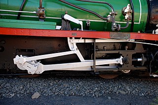
The valve gear of a steam engine is the mechanism that operates the inlet and exhaust valves to admit steam into the cylinder and allow exhaust steam to escape, respectively, at the correct points in the cycle. It can also serve as a reversing gear. It is sometimes referred to as the "motion".

<span class="mw-page-title-main">Variable valve timing</span> Process of altering the timing of a valve lift event

Variable valve timing (VVT) is the process of altering the timing of a valve lift event in an internal combustion engine, and is often used to improve performance, fuel economy or emissions. It is increasingly being used in combination with variable valve lift systems. There are many ways in which this can be achieved, ranging from mechanical devices to electro-hydraulic and camless systems. Increasingly strict emissions regulations are causing many automotive manufacturers to use VVT systems.

<span class="mw-page-title-main">Walschaerts valve gear</span> Type of valve gear

The Walschaerts valve gear is a type of valve gear used to regulate the flow of steam to the pistons in steam locomotives, invented by Belgian railway engineer Egide Walschaerts in 1844. The gear is sometimes named without the final "s", since it was incorrectly patented under that name. It was extensively used in steam locomotives from the late 19th century until the end of the steam era.

<span class="mw-page-title-main">Automatic lubricator</span> Device fitted to a steam engine to supply lubricating oil

An automatic lubricator is a device fitted to a steam engine to supply lubricating oil to the cylinders and, sometimes, the bearings and axle box mountings as well. There are various types of automatic lubricator, which include various designs of displacement, hydrostatic and mechanical lubricators.

<span class="mw-page-title-main">Stephenson valve gear</span> Simple design of valve gear

The Stephenson valve gear or Stephenson link or shifting link is a simple design of valve gear that was widely used throughout the world for various kinds of steam engines. It is named after Robert Stephenson but was invented by his employees.

In a steam engine, cutoff is the point in the piston stroke at which the inlet valve is closed. On a steam locomotive, the cutoff is controlled by the reversing gear.

<span class="mw-page-title-main">Corliss steam engine</span> Type of steam engine using rotary steam valves

A Corliss steam engine is a steam engine, fitted with rotary valves and with variable valve timing patented in 1849, invented by and named after the US engineer George Henry Corliss of Providence, Rhode Island.

<span class="mw-page-title-main">Southern valve gear</span>

Southern valve gear was briefly popular on steam locomotives in the United States. It combines elements of the Walschaerts and Baker patterns.

<i>Mastodon</i> (steam locomotive)

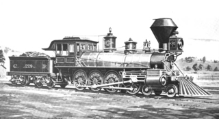
Mastodon was the unofficial name of the Central Pacific Railroad's number 229, the world's first successful 4-8-0 steam locomotive.

<span class="mw-page-title-main">Bagnall–Price valve gear</span>

Bagnall–Price valve gear is a type of steam engine valve gear developed at locomotive manufacturer W.G. Bagnall as an alternative to the more common Walschaerts valve gear and also to supersede the Baguley valve gear their designs had previously utilised. The gear was patented in 1903 by W.G. Bagnall and T. S. Price, the manager of the works.

<span class="mw-page-title-main">Cylinder (locomotive)</span> Power-producing element of a steam locomotive

The cylinder is the power-producing element of the steam engine powering a steam locomotive. The cylinder is made pressure-tight with end covers and a piston; a valve distributes the steam to the ends of the cylinder. Cylinders were initially cast iron, but later made of steel. The cylinder casting includes other features such as valve ports and mounting feet. The last big American locomotives incorporated the cylinders as part of huge one-piece steel castings that were the main frame of the locomotive. Renewable wearing surfaces were needed inside the cylinders and provided by cast-iron bushings.

<span class="mw-page-title-main">Piston valve (steam engine)</span> Form of valve within a steam engine or locomotive

Piston valves are one form of valve used to control the flow of steam within a steam engine or locomotive. They control the admission of steam into the cylinders and its subsequent exhausting, enabling a locomotive to move under its own power. The valve consists of two piston heads on a common spindle moving inside a steam chest, which is essentially a mini-cylinder located either above or below the main cylinders of the locomotive.

The EDWARD BURY to PFEIL series of early German locomotives were tender engines operated by the Leipzig–Dresden Railway Company.

<span class="mw-page-title-main">Reversing gear</span> Controller for the valves on a steam engine

On a steam locomotive, the reversing gear is used to control the direction of travel of the locomotive. It also adjusts the cutoff of the steam locomotive.

<span class="mw-page-title-main">Gab valve gear</span>

Gab valve gear was an early form of valve gear used on steam engines. Its simplest form allowed an engine to be stopped and started. A double form, mostly used on steam locomotives, allowed easy reversing.

<span class="mw-page-title-main">High-speed steam engine</span> Steam engine designed to run at comparatively high speed

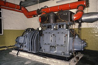
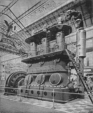
High-speed steam engines were one of the final developments of the stationary steam engine. They ran at a high speed, of several hundred rpm, which was needed by tasks such as electricity generation.

A bash valve is a valve within a piston engine, used to control the admission of the working fluid. They are directly actuated valves, operated by contact between the piston and the valve tip.

References

  1. 1 2 3 4 5 Evers, Henry (1875). Steam and the Steam Engine: Land and Marine. Glasgow: Williams Collins. pp. 78–81.
  2. 1 2 3 Evers (1875), pp. 51–53.
  3. Hills 1989 , p. 102
  4. Trevithick, Francis (1872). Life of Richard Trevithick with an Account of his Inventions. Vol. II. p. 132.
  5. Evers (1875), pp. 73–74.
  6. Southworth (1986) , p. 26
  7. 1 2 Hills 1989 , p. 188
  8. 1 2 Hills 1989 , pp. 226–227
  9. Hawkins, Nehemiah (1897). New Catechism of the Steam Engine. New York: Theo Audel. pp.  97–99.
  10. GB 3207,published 1869-11-05
  11. GB 9571,James Morris,published 1842-12-22
  12. Southworth, P.J.M. (1986). Some Early Robey Steam Engines. P.J.M. Southworth. pp. 4, 21–22, 24. ISBN   0-9511856-0-8.
  13. "The expansion slide valve and governors". Old Engine House. Archived from the original on 2012-02-04. Retrieved 2012-03-30.
  14. Hills, Richard L. (1989). Power from Steam. Cambridge University Press. p. 174. ISBN   0-521-45834-X.
  15. Robey & Co. engine of 1887 Southworth (1986) , pp. 21–22, 24
  16. Evers (1875) , p. 78
  17. GB 14753,John Richardson,published 1885
  18. "The Richardson Governor". Old Engine House. Archived from the original on 2011-09-19. Retrieved 2012-03-30.
  19. Southworth (1986) , p. 20
  20. Ahrons, E.L. (1966). The British Steam Railway Locomotive. Vol. I, to 1925. Ian Allan. p. 345.
  21. Self, Douglas (8 February 2004). "The Paget Locomotive". Loco Loco gallery.
  22. Critical Reports. "Automotive Electronic Expansion Valve Market Research Report Provides thorough Industry Overview, which offers an In-Depth Analysis of Product Trends".