Return connecting rod engine

Last updated
Trevithick's stationary engine of 1806 Trevithick high pressure engine of 1806.jpg
Trevithick's stationary engine of 1806

A return connecting rod, [1] [2] return piston rod [lower-roman 1] or (in marine parlance) double piston rod engine [2] or back-acting engine is a particular layout for a steam engine.

Contents

The key attribute of this layout is that the piston rod emerges from the cylinder to the crosshead, but the connecting rod then reverses direction and goes backwards to the crankshaft. This layout is compact, but has mechanical disadvantages. Return connecting rod engines were thus rarely used.

The return connecting rod layout has two possible forms:

Both horizontal and vertical arrangements have used the return connecting rod layout. Vertical return connecting rod engines used the original 'vertical' layout, with the cylinder facing upwards to the crosshead. [lower-roman 2]

Table and Steeple engines

Model table engine, showing the forked connecting rod Coombes' table engine, Abergavenny steam rally 2012.jpg
Model table engine, showing the forked connecting rod

'Table' and 'steeple' engines are vertical stationary engines with return connecting rods.

Table engines

Table engines place the cylinder above and between the crankshaft and the crosshead. They saw widespread manufacture by Maudslay from around 1805 and were used to supply power to small engineering workshops. They were especially popular for driving lineshafting, as they could operate at a higher speed than beam engines.

Like the smaller grasshopper beam engines, an advantage for Maudslay's table engines was that they could be made in factories as a complete unit. This included their large cast iron baseplate or table. Unlike horizontal engines and house-built beam engines, they did not require the construction of a large and carefully aligned masonry foundation at the engine's site. Engines could also be made in advance and sold 'off the shelf'. Although this had cost savings, it was mostly beneficial because it was quicker than commissioning the building of an engine and engine house to go with it.

Steeple engines

Steeple engine Steeple engine (Steam and the Steam Engine, Evers).jpg
Steeple engine

Steeple engines place the crankshaft above the cylinder, between it and the crosshead. They use paired piston rods, two or even four, from the piston to the crosshead, to avoid the crankshaft. Another pattern used a triangular yoke on the single piston rod, allowing the crankshaft to pass through it. [4]

Steeple engines were mostly used as marine engines. [1] [5] Some American paddlewheel riverboats had especially large steeples that towered over their deckhouse.

The term 'steeple engine' was also used later to refer to inverted-vertical tandem-compound engines, owing to their great height. [lower-roman 3] These were not return connecting rod engines.

Locomotives

Steam Elephant (replica) Historic railway in the Beamish Museum 06.JPG
Steam Elephant (replica)

Trevithick's first high-pressure engines from 1801 onwards, including his locomotives, used the return connecting rod layout in both horizontal and vertical arrangements. The cylinders were embedded within the boiler, to avoid heat loss, and the short boiler also formed the frame of the engine. This made the return connecting rod a natural layout, with the crankshaft at the opposite end of the boiler from the crosshead. The paired connecting rods were relatively simple components, even though two were required. As they also allowed the crankshaft to use two simple overhung cranks on the ends of the shaft, rather than a complex forged crankshaft with an internal crank, this was also a valuable simplification.

Other early steam locomotives such as Murray's Salamanca (1812) and George Stephenson's Blücher (1815) and Locomotion (1825) also used return connecting rod engines. These all had heavy vertical cylinders set in tandem within the boiler barrel, driving through transverse crossheads above the locomotive, supported by swinging links. The complexity of this motion led to it being named 'the knitting' by drivers. The swinging link was simpler than Watt's earlier parallel motion and did not constrain the crosshead to move in such an accurate straight line. However the additional length of the connecting rods for a return connecting rod engine, relative to the piston stroke, made this angulation effect less serious. The Steam Elephant used a rudimentary set of slidebars to support the crosshead instead.

The use of a return connecting rod to a shaft beneath the boiler with overhung cranks also avoided the need for an internal crank. For Stephenson's designs, this crank axle would also have carried the locomotive's weight, not being merely a crankshaft, and so this avoided a particularly difficult piece of forging work.

One of the last locomotives to use return connecting rods was Ericsson and Braithwaite's Novelty at the Rainhill trials.

Abandonment of return connecting rod designs

Hedley's Puffing Billy, a contemporary of Blücher, avoided the return connecting rod in favour of a grasshopper beam. The cylinders were now mounted side by side, but were still large, heavy and mounted as an integral part of the boiler. Although a beam engine has a similar layout to a return connecting rod engine, in that the piston rod points in one direction and the connecting rod runs backwards from this, beam engines are not considered as return connecting rod engines. Stephenson's manager Hackworth's locomotive Royal George inverted the design to having the cylinders, still vertical, face downwards directly onto the crankshaft. By the time of Stephenson's Rocket, particularly as the new fire-tube boiler locomotives became lighter and faster, it was recognised that vertical cylinders caused hammer blow on the flimsy fishbelly rails of the time. Rocket was built with cylinders inclined at 45° but was soon rebuilt to place them near-horizontally. Since then, almost all steam locomotives have had their cylinders placed close to horizontal.

Marine steam engines

Paddle ships

Crosshead ("square") engine of the Hudson River steamboat PS Belle Crosshead engine diagram of PS Belle.jpg
Crosshead ("square") engine of the Hudson River steamboat PS Belle

The first marine steam engines drove paddlewheels. Paddles require a relatively high axle, that often also forms the crankshaft. For stability the main weight of the engine, i.e. its cylinder, is mounted low down. Later engines drove single screw propellers. These now required a low-mounted drive, but still benefited from the stability effect of a low-set engine. Such early engines, constrained by the technology of the time, worked at low boiler pressures and slow piston speeds. Together with the short piston stroke constrained by lack of space for the engine, [lower-roman 4] these early engines required large diameter pistons in order to develop enough power.

Crosshead engines

Crosshead, 'double crosshead' [1] or 'square' engines were vertical engines analogous in layout to the table engine, with their cylinder above the crankshaft. The crosshead needed to be very wide, to allow the connecting rods to pass either side of the large cylinder, which in turn required a large supporting frame for the slidebars. They were popular for early American riverboats and their large wooden A frame crosshead supports were a distinctive feature. [6] Larger engines became top-heavy and so the design was replaced by steeple or walking beam engines.

Steeple engines

European practice, particularly on the Clyde, favoured Napier's steeple engine instead of the square engine. These were more complicated to construct and used more ironwork, but they placed the cylinder beneath the crankshaft and so were more stable in a narrow hull. Neither form was popular for sea-going vessels. [1] [4] [5]

Screw propulsion

In marine practice, the return connecting rod engine for screw propulsion was termed the back-acting [1] (US parlance) or double piston rod [2] engine.

Trunk engines

John Penn patented the trunk engine in 1848. This was a design to allow a particularly short engine (measured in the direction of its piston rod), that was also able to support a large diameter piston. [lower-roman 5] They were mounted transversely, usually as two cylinder engines, and used for naval ships with relatively high installed power. A trunk engine achieves its short length by having a large diameter, hollow piston rod or 'trunk'. The gudgeon pin of the connecting rod is mounted inside this trunk, allowing the overall length of the two man components, the piston rod and connecting rod, to be telescoped together. As the trunk must be large enough to allow for the angulation of the connecting rod as the crank rotates, this design is limited to large diameter engines. It was also found that as boiler pressure increased, the large diameter seal around the trunk was increasingly prone to leaking. [7]

Double piston rod engines

Double piston rod engine of screw-driven HMS Agincourt (1865)
Cylinder and piston are to the right, condenser and air pump to the left. HMS Agincourt engine.jpg
Double piston rod engine of screw-driven HMS Agincourt (1865)
Cylinder and piston are to the right, condenser and air pump to the left.

The trunk engine was largely replaced by the double piston-rod engine. [2] [8] This was a return connecting rod engine, with the crankshaft between the crosshead and cylinder. Four piston rods were used to pass around the crankshaft, both above and below, and also to each side of the crank, as the crank throw was wider than the vertical spacing of the piston rods. As most of these engines were parallel compounds, two piston rods would be taken from each of the HP and LP pistons. In some engines, double rods were used from the large LP cylinder and a single rod from the HP cylinder, with a yoke to pass around the crankshaft. [9] Double piston rods could also be used from a simple engine, but these required an overhung gudgeon pin on the crosshead, so tended to be limited to smaller engines. An advantage of the double piston rod engine over the trunk was that both ends of the connecting rod were accessible for maintenance. One factor learned from naval use of horizontal cylinders was that, despite previous fears, there was little additional wear owing to the piston's weight resting on the cylinder. [2]

An Admiralty committee of 1858 recommended strongly that older engine designs be abandoned in favour of rationalisation on only three designs: the single piston rod engine (the most recognisable type today), the trunk engine and the double piston rod. [10]

A later variant of the trunk engine re-visited the return connecting rod layout as the vibrating lever or half-trunk engine. This was a paired engine with two short-stroke trunk engines facing outwards. Their connecting rods from the pistons led to upright 'vibrating levers' that could rock back and forth. These levers rotated a short axle shaft with further levers on it that in turn drove another pair of connecting rods and a shared central crankshaft. These complex engines were the invention of the Swedish-American engineer John Ericsson and were little used outside these two countries.

Maudslay's siamese engine

Other compact alternatives to the return connecting rod or trunk engines were Maudslay's siamese engine [11] and the rare annular piston engine. Like the trunk engine, these placed the gudgeon pin within the length of the piston stroke by having a pair of pistons and a T-shaped crosshead that could relocate the gudgeon pin behind its usual position.

Builders

Directly coupled pumps and blowing engines

Vertical blowing engine Allis blowing engine (New Catechism of the Steam Engine, 1904).jpg
Vertical blowing engine

A blowing engine is a large stationary steam engine directly coupled to air pumping cylinders. They are used to provide the air blast for blast furnaces and other forms of smelter. As the working cylinder and the driven load are both reciprocating pistons, they may be directly coupled by their piston rod. The connecting rod is only used to drive a flywheel whose inertia balances load through the cycle of the engine, not as an output shaft. These engines were some of the last new return connecting rod designs to be built.

The large vertical blowing engine illustrated was built in the 1890s by E. P. Allis Co. of Milwaukee (later to form part of Allis-Chalmers). [12] The air pumping cylinder is above the steam power cylinder and crosshead. The main force of the piston is transmitted to the air cylinder by a purely reciprocating action and the flywheels are there merely to smooth the action of the engine. The flywheel shaft is mounted below the steam piston, the paired connecting rods driving downwards and backwards.

Similar pumping engines were also used in waterworks. Inverted vertical engines had their cylinder at the top and water ram pumps at their base, or in a borehole below them. A crankshaft and flywheels were provided in the space between these, for smoother running rather than rotary power output. These were driven from the lower (pump) yoke, by short return connecting rods. Two Worth McKenzie engines of this type; a triple-expansion engine on 1895 and a duplex simple of 1906 were installed at the Waterworks Museum, Hereford, Hereford and are preserved in steam there.

Notes

  1. 'Return piston rod' was a term used by naval engine builders Humphrys and Tennant. [3]
  2. Although rare today, this was the original layout for all atmospheric and steam engines. The cylinder sat directly atop the boiler below. Even with the development of separate boilers, it was still considered simpler for access to place the large, heavy cylinder low down and with the lighter cranks above. The form of vertical engine that became more common in later years, with the cylinder facing downwards, was originally termed the 'inverted vertical'.
  3. A tandem compound places both high and low pressure cylinders, sometimes even a third intermediate pressure cylinder, in-line on the same piston rod.
  4. American sternwheel paddlesteamers used longitudinal horizontal engines that allowed a long stroke. These developed as long, small diameter engines of a distinctly different pattern from any other marine engines. In contrast, American sidewheel paddlesteamers favoured particularly tall upright steeple or walking beam engines.
  5. A prevalent theory at the time was concerned about the effects of wear on the pistons of horizontal engines, owing to the weight of the piston. Pistons were thus provided with extensive support from their piston and tail rods, rather than allowing any weight to rest directly on the cylinder wall.

Related Research Articles

Piston

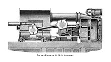
A piston is a component of reciprocating engines, reciprocating pumps, gas compressors, hydraulic cylinders and pneumatic cylinders, among other similar mechanisms. It is the moving component that is contained by a cylinder and is made gas-tight by piston rings. In an engine, its purpose is to transfer force from expanding gas in the cylinder to the crankshaft via a piston rod and/or connecting rod. In a pump, the function is reversed and force is transferred from the crankshaft to the piston for the purpose of compressing or ejecting the fluid in the cylinder. In some engines, the piston also acts as a valve by covering and uncovering ports in the cylinder.

Crosshead

A crosshead is a mechanism used as part of the slider-crank linkages of long reciprocating engines and reciprocating compressors to eliminate sideways pressure on the piston. Also, the crosshead enables the connecting rod to freely move outside the cylinder. Because of the very small bore-to-stroke ratio on such engines, the connecting rod would hit the cylinder walls and block the engine from rotating if the piston was attached directly to the connecting rod like on trunk engines. Therefore, the longitudinal dimension of the crosshead must be matched to the stroke of the engine.

Valve gear Mechanism for controlling steam flow in a reciprocating steam engine.

The valve gear of a steam engine is the mechanism that operates the inlet and exhaust valves to admit steam into the cylinder and allow exhaust steam to escape, respectively, at the correct points in the cycle. It can also serve as a reversing gear. It is sometimes referred to as the "motion".

Connecting rod

A connecting rod is the part of a piston engine which connects the piston to the crankshaft. Together with the crank, the connecting rod converts the reciprocating motion of the piston into the rotation of the crankshaft. The connecting rod is required to transmit the compressive and tensile forces from the piston. In its most common form, in an internal combustion engine, it allows pivoting on the piston end and rotation on the shaft end.

Stationary steam engine Fixed steam engine for pumping or power generation

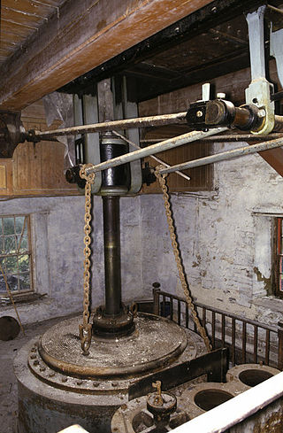
Stationary steam engines are fixed steam engines used for pumping or driving mills and factories, and for power generation. They are distinct from locomotive engines used on railways, traction engines for heavy steam haulage on roads, steam cars, agricultural engines used for ploughing or threshing, marine engines, and the steam turbines used as the mechanism of power generation for most nuclear power plants.

Table engine

A table engine is a variety of stationary steam engine where the cylinder is placed on top of a table-shaped base, the legs of which stand on the baseplate which locates the crankshaft bearings. The piston rod protrudes from the top of the cylinder and has fixed to it a cross-head which runs in slides attached to, and rising from, the cylinder top. Long return rods connect the crosshead to the crankshaft, on which is fixed the flywheel.

Compound steam engine

A compound steam engine unit is a type of steam engine where steam is expanded in two or more stages. A typical arrangement for a compound engine is that the steam is first expanded in a high-pressure (HP) cylinder, then having given up heat and losing pressure, it exhausts directly into one or more larger-volume low-pressure (LP) cylinders. Multiple-expansion engines employ additional cylinders, of progressively lower pressure, to extract further energy from the steam.

Piston rod

In a piston engine, a piston rod joins a piston to the crosshead and thus to the connecting rod that drives the crankshaft or the driving wheels.

Engine balance refers to how the forces are balanced within an internal combustion engine or steam engine. The most commonly used terms are primary balance and secondary balance. Unbalanced forces within the engine can lead to vibrations.

Leavitt-Riedler Pumping Engine

The Leavitt-Riedler Pumping Engine (1894) is a historic steam engine located in the former Chestnut Hill High Service Pumping Station, in Boston, Massachusetts. It has been declared a historic mechanical engineering landmark by the American Society of Mechanical Engineers. The pumping station was decommissioned in the 1970s, and turned into the Metropolitan Waterworks Museum in 2011.

Marine steam engine

A marine steam engine is a steam engine that is used to power a ship or boat. This article deals mainly with marine steam engines of the reciprocating type, which were in use from the inception of the steamboat in the early 19th century to their last years of large-scale manufacture during World War II. Reciprocating steam engines were progressively replaced in marine applications during the 20th century by steam turbines and marine diesel engines.

Blowing engine

A blowing engine is a large stationary steam engine or internal combustion engine directly coupled to air pumping cylinders. They deliver a very large quantity of air at a pressure lower than an air compressor, but greater than a centrifugal fan.

Musgrave non-dead-centre engine

Musgrave's non-dead-centre engine was a stationary steam engine of unusual design, intended to solve the problem of stopping on dead centre. It was designed in 1887 to serve as a marine engine. It used a pair of linked cylinders to prevent the engine from stopping in a position where no turning force can be applied. At least one engine is known to survive.

Steam motor

A steam motor is a form of steam engine used for light locomotives. They represented one of the final developments of the steam locomotive, in the final decades of the widespread use of steam power.

Grasshopper beam engine

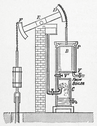
Grasshopper beam engines are beam engines that are pivoted at one end, rather than in the centre.

House-built engine

A house-built engine is a stationary steam engine that is built into an engine house, such that it uses the masonry of the engine house as an integral part of the support of the engine.

Single- and double-acting cylinders

Reciprocating engine cylinders are often classified by whether they are single- or double-acting, depending on how the working fluid acts on the piston.

High-speed steam engine

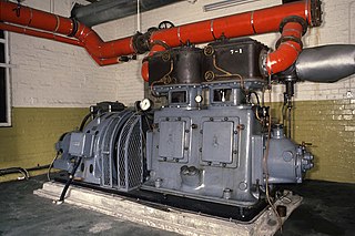
High-speed steam engines were one of the final developments of the stationary steam engine. They ran at a high speed, of several hundred rpm, which was needed by tasks such as electricity generation.

Willans engine

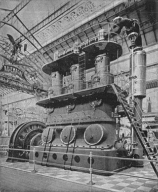
The Willans engine or central valve engine was a high-speed stationary steam engine used mainly for electricity generation around the start of the 20th century.

Stuart Turner Ltd is a British engineering company, based in Henley-on-Thames, Oxfordshire, England, founded by engineer Sidney Marmaduke Stuart Turner in 1906.

References

  1. 1 2 3 4 5 Rippon, P.M. (1998). The evolution of engineering in the Royal Navy. 1: 1827-1939. Spellmount. p. 27. ISBN   0-946771-55-3.
  2. 1 2 3 4 5 Hills, Richard L. (1989). Power from Steam. Cambridge University Press. pp. 189, 191. ISBN   0-521-45834-X.
  3. Brown, David K. (2010) [1997]. Warrior to Dreadnought. Seaforth. p. 13. ISBN   978-1-84832-086-4.
  4. 1 2 Luke Hebert, ed. (1849). The Steeple Engine. The Engineer's and Mechanic's Encyclopaedia. 2 (2nd ed.). Thomas Kelly.
  5. 1 2 Evers, Henry (1875). Steam and the Steam Engine: Land and Marine. Glasgow: Williams Collins. p. 95.
  6. Hilton, George W. (2002). Lake Michigan Passenger Steamers. Stanford University Press. p. 59. ISBN   978-0804742405.
  7. Seaton, A.E. (1888). A Manual of Marine Engineering (7th ed.). London. p. 9.
  8. Sennett, Richard; Oram, Sir Henry J. (1918). The Marine Steam Engine. London: Longmans, Green & Co. pp. 7, 9.
  9. "Emery Rice T. V. Engine (1873)" (PDF). American Society of Mechanical Engineers. Archived from the original (PDF) on 2008-12-09.
  10. Smith, E.C. (1937). A Short History of Naval and Marine Engineering. Cambridge. pp. 146–147.
  11. Evers (1875), p. 96.
  12. Hawkins, Nehemiah (1897). New Catechism of the Steam Engine. New York: Theo Audel. pp. 335–337.