

A house-built engine is a stationary steam engine that is built into an engine house, such that it uses the masonry of the engine house as an integral part of the support of the engine. [1]
A house-built engine is a stationary steam engine that is built into an engine house, such that it uses the masonry of the engine house as an integral part of the support of the engine. [1]


Most house-built engines were early beam engines. A 'bob wall' [2] in the engine house supported the pivot axle of the beam or 'bob'. [3] This wall could be an internal wall, with both ends of the beam inside the house, but it was commonly the end wall of the house and so the beam projected to the outside. For a heavy beam, the bob wall was required to be extremely substantial. Early engines were used for pumping mines or wells, so as well as the weight of the beam, the house had to also support the weight of the long pump rod, reaching down to the depths of the mine. [4]
Beam engines appeared during the 18th century. The only technologies at this time that could support the weight of an engine's beam were masonry and timber-framing, as the work of either shipwrights or millwrights. Cast iron was not yet a structural material, or capable of being worked at this scale. Wrought iron was too expensive to be used in such sizes.
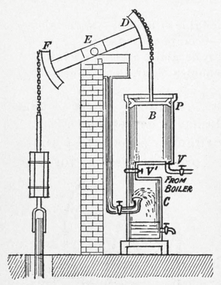
After the early beam engines, where the cylinder was mounted directly atop the boiler, the space inside the house of later beam engines was divided by floors. The 'bottom chamber' contained the base of the cylinder, the lower valves and the valvegear. This was the main working chamber and was where the engine driver would spend most of their time. [5] Above this, a floor or partial floor and the 'top chamber' provided a working space for access to the valves or 'nozzles' at the top of the cylinder. This was used mostly for intermittent access to lubricate bearings etc. Often the floor did not span the full length of the house and formed a gallery above the bottom chamber. These floors and stairways were often fitted with woodwork and banisters of the highest quality. Similarly the 'beam chamber' at the top of the house provided access to the beam's bearings. Where the beam extended through the end wall of the house, two small outdoor platforms on either side of the beam gave access from the beam chamber to each side of the beam and the bearings for the pump shaft. [5] A final chamber was beneath the floor of the bottom chamber. This contained the air pump and regulating cataract. It was so rarely visited that access was only by means of a trapdoor.

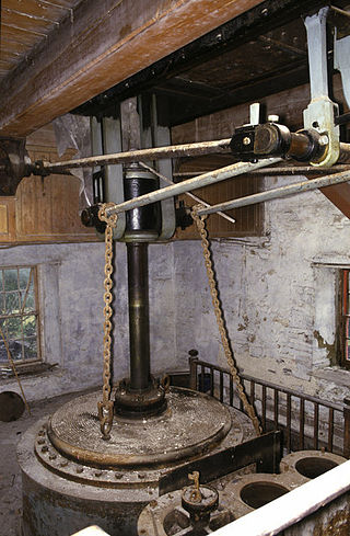
Small vertical engines were also house-built. An engine of this type, from Sunnybank Mill, has been preserved near Darwen. [6]
One of the first engines to avoid the need for house-building was the table engine, from around 1800. This vertical engine placed the cylinder above the crankshaft and the crosshead above that, with a return connecting rod. Although Sadler's first table engine was house-built, Maudslay's patent table engine sat the cylinder upon a cast iron table, giving the engine its name. This table was independent of the engine house. Provided that the floor was strong enough to support the weight of the engine and was reasonably level, these engines could be placed anywhere, without needing special houses to be built for them.
Such construction was also quicker to build on-site, as a pre-manufactured engine could be supplied by the engine maker in almost completed form. Skilled engine erectors were a rare resource, especially in remote mining areas, and the need to have them working on-site for long periods whilst a large house was constructed around the engine was often a cause of delays to an engine being completed. [7] Even with adequate labour, masonry construction is a slower process than delivery of machinery alone. Where brick foundations were constructed, it was recommended that at least fifteen days were allowed before the weight of the engine was placed onto them. [8]
With the development of the horizontal stationary engine in the mid 19th century, the requirements were no longer to support a single heavy beam but now to provide accurate alignment between the cylinders and crankshaft of a medium-speed engine. [9] These foundations were substantial, going down perhaps three-dozen courses of brickwork below the engine bed. Deep iron anchors were provided within the brickwork for the engine to be bolted down. Rough local stone was no longer rigid enough and so foundations were constructed of many layers of hard engineering brick, as this was cheaper and more easily available than a cut ashlar stone of equal rigidity. [10] As these engine ran at faster speeds than the beam engines, their vibration could also be higher requiring a foundation that could withstand such. Alignment between slideways and crankshaft depended upon the original care with which the foundation had been built.

The girder bed engine avoided some of this dependency by providing the engine with a single long bed casting that spanned the crankshaft and trunk guide. The bed was connected to its plinth by a number of short pillars. [10] Although this bed still required care during erection to avoid twisting by clamping it down too firmly to a misaligned foundation, it did simplify engine alignment and also reduced effects if the foundation settled in service.
Where high-speed steam engines were used, these small engines usually incorporated a single-piece cast iron bed. This could be supported by a single brickwork pier, without needed careful alignment by its masons. [10] Some engine makers, such as Robey & Co. of Lincoln, developed a distinctive form of cantilevered cast iron bed for their large medium speed engines that formed both the crosshead trunk guide and the crank bearings, thus permitting a similar single plinth foundation. [11]

House building for beam engines continued into the 20th century.
One of the largest sets of engines installed in a single engine house were the six engines for pumping the completed Severn Tunnel in 1886. These had six beams, arranged radially around the tunnel shaft, and passing in two groups of three through a pair of internal walls, just above ground level. [12]
The last Cornish engine built, at Dorothea Quarry in 1905, [2] has a through-wall beam supported on a wall 5 ft 6in thick.

A piston is a component of reciprocating engines, reciprocating pumps, gas compressors, hydraulic cylinders and pneumatic cylinders, among other similar mechanisms. It is the moving component that is contained by a cylinder and is made gas-tight by piston rings. In an engine, its purpose is to transfer force from expanding gas in the cylinder to the crankshaft via a piston rod and/or connecting rod. In a pump, the function is reversed and force is transferred from the crankshaft to the piston for the purpose of compressing or ejecting the fluid in the cylinder. In some engines, the piston also acts as a valve by covering and uncovering ports in the cylinder.

In mechanical engineering, a crosshead is a mechanical joint used as part of the slider-crank linkages of long reciprocating engines and reciprocating compressors to eliminate sideways force on the piston. Also, the crosshead enables the connecting rod to freely move outside the cylinder. Because of the very small bore-to-stroke ratio on such engines, the connecting rod would hit the cylinder walls and block the engine from rotating if the piston was attached directly to the connecting rod like on trunk engines. Therefore, the longitudinal dimension of the crosshead must be matched to the stroke of the engine.

A connecting rod, also called a 'con rod', is the part of a piston engine which connects the piston to the crankshaft. Together with the crank, the connecting rod converts the reciprocating motion of the piston into the rotation of the crankshaft. The connecting rod is required to transmit the compressive and tensile forces from the piston. In its most common form, in an internal combustion engine, it allows pivoting on the piston end and rotation on the shaft end.

Stationary steam engines are fixed steam engines used for pumping or driving mills and factories, and for power generation. They are distinct from locomotive engines used on railways, traction engines for heavy steam haulage on roads, steam cars, agricultural engines used for ploughing or threshing, marine engines, and the steam turbines used as the mechanism of power generation for most nuclear power plants.

A table engine is a variety of stationary steam engine where the cylinder is placed on top of a table-shaped base, the legs of which stand on the baseplate which locates the crankshaft bearings. The piston rod protrudes from the top of the cylinder and has fixed to it a cross-head which runs in slides attached to, and rising from, the cylinder top. Long return rods connect the crosshead to the crankshaft, on which is fixed the flywheel.
In a piston engine, a piston rod joins a piston to the crosshead and thus to the connecting rod that drives the crankshaft or the driving wheels.
A beam engine is a type of steam engine where a pivoted overhead beam is used to apply the force from a vertical piston to a vertical connecting rod. This configuration, with the engine directly driving a pump, was first used by Thomas Newcomen around 1705 to remove water from mines in Cornwall. The efficiency of the engines was improved by engineers including James Watt, who added a separate condenser; Jonathan Hornblower and Arthur Woolf, who compounded the cylinders; and William McNaught, who devised a method of compounding an existing engine. Beam engines were first used to pump water out of mines or into canals but could be used to pump water to supplement the flow for a waterwheel powering a mill.

Walka Water Works is a heritage-listed 19th-century pumping station at 55 Scobies Lane, Oakhampton Heights, City of Maitland, New South Wales, Australia. Originally built in 1887 to supply water to Newcastle and the lower Hunter Valley, it has since been restored and preserved and is part of Maitland City Council's Walka Recreation and Wildlife Reserve. It was added to the New South Wales State Heritage Register on 2 April 1999.

A marine steam engine is a steam engine that is used to power a ship or boat. This article deals mainly with marine steam engines of the reciprocating type, which were in use from the inception of the steamboat in the early 19th century to their last years of large-scale manufacture during World War II. Reciprocating steam engines were progressively replaced in marine applications during the 20th century by steam turbines and marine diesel engines.

A semi-portable engine is a form of stationary steam engine. They were built in a factory as a single unit including the boiler, so that they could be rapidly installed on site and brought into service.

Grasshopper beam engines are beam engines that are pivoted at one end, rather than in the centre.

A return connecting rod, return piston rod or double piston rod engine or back-acting engine is a particular layout for a steam engine.
High-speed steam engines were one of the final developments of the stationary steam engine. They ran at a high speed, of several hundred rpm, which was needed by tasks such as electricity generation.

A steeple compound engine is a form of tandem compound steam engine that is constructed as an inverted vertical engine. Because of their great height, they became known as "steeple" engines.
The Vincent lifeboat engine was a unique design of two-stroke petrol engine. It was developed during World War II as a highly efficient engine for airborne lifeboats, providing a long range from little fuel.

Six-column beam engines are a type of beam engine, where the beam's central pivot is supported on a cast-iron frame or 'bedstead', supported on six iron columns.

Fairbottom Bobs is a Newcomen-type beam engine that was used in the 18th century as a pumping engine to drain a colliery near Ashton-under-Lyne. It is probably the world's second-oldest surviving steam engine. The engine was installed at Cannel Colliery at Fairbottom near Ashton-under-Lyne around 1760 or 1764. It became known locally as Fairbottom Bobs.

The 4 VD 14,5/12-1 SRW is an inline four-cylinder diesel engine produced by the VEB IFA Motorenwerke Nordhausen from 1967 to 1990. The engine was one of the standard modular engines for agricultural and industrial use in the Comecon-countries. Approximately one million units were made.
Stuart Turner Ltd is a British engineering company, based in Henley-on-Thames, Oxfordshire, England, founded by engineer Sidney Marmaduke Stuart Turner in 1906.

Willemsoord Dry Dock I is a historic dry dock in Willemsoord, Den Helder, Netherlands. It was constructed from 1813 till 1822, under the direction of Jan Blanken, and was part of the former Rijkswerf Willemsoord.