Cylinder (locomotive)

Last updated

The 'motion' on the left-hand side of 60163 Tornado. The black casting to the left houses the cylinder, in which slides the piston; the piston rod is immediately above the wheel. 60163 Tornado cylinder rod.jpg
The 'motion' on the left-hand side of 60163 Tornado. The black casting to the left houses the cylinder, in which slides the piston; the piston rod is immediately above the wheel.

The cylinder is the power-producing element of the steam engine powering a steam locomotive. The cylinder is made pressure-tight with end covers and a piston; a valve distributes the steam to the ends of the cylinder. Cylinders were initially cast iron, but later made of steel. The cylinder casting includes other features such as (in the case of Stephenson's Rocket) valve ports and mounting feet. [1] The last big American locomotives incorporated the cylinders as part of huge one-piece steel castings that were the main frame of the locomotive. [2] Renewable wearing surfaces were needed inside the cylinders and provided by cast-iron bushings.

Contents

The way the valve controlled the steam entering and leaving the cylinder was known as steam distribution and shown by the shape of the indicator diagram. What happened to the steam inside the cylinder was assessed separately from what happened in the boiler and how much friction the moving machinery had to cope with. This assessment was known as "engine performance" or "cylinder performance". The cylinder performance, together with the boiler and machinery performance, established the efficiency of the complete locomotive. The pressure of the steam in the cylinder was measured as the piston moved and the power moving the piston was calculated and known as cylinder power. The forces produced in the cylinder moved the train but were also damaging to the structure which held the cylinders in place. Bolted joints came loose, cylinder castings and frames cracked and reduced the availability of the locomotive.

Cylinders may be arranged in several different ways.

Early locomotives

On early locomotives, such as Puffing Billy , the cylinders were often set vertically and the motion was transmitted through beams, as in a beam engine.

Direct drive

French 2-2-2 locomotive with nearly horizontal cylinders, 1844 Locomotive ndeg 0135 de la Cie de l'Ouest.jpg
French 2-2-2 locomotive with nearly horizontal cylinders, 1844

The next stage, for example Stephenson's Rocket , was to drive the wheels directly from steeply inclined cylinders placed at the back of the locomotive. Direct drive became the standard arrangement, but the cylinders were moved to the front and placed either horizontal or nearly horizontal.

Inside or outside cylinders

The front-mounted cylinders could be placed either inside (between the frames) or outside. Examples of each are:

In the 19th and early 20th centuries, inside cylinders were widely used in the United Kingdom, but outside cylinders were more common in Continental Europe and the United States. The reason for this difference is unclear.[ citation needed ] From about 1920, outside cylinders became more common in the UK but many inside-cylinder engines continued to be built. Inside cylinders give a more stable ride with less yaw or "nosing" but access for maintenance is more difficult. Some designers used inside cylinders for aesthetic reasons.

Three or four cylinders

The demand for more power led to the development of engines with three cylinders (two outside and one inside) or four cylinders (two outside and two inside). Examples:

Crank angles

On a two-cylinder engine the cranks, whether inside or outside, are set at 90 degrees. As the cylinders are double-acting (i.e. fed with steam alternately at each end) this gives four impulses per revolution and ensures that there are no dead centres.

On a three-cylinder engine, two arrangements are possible:

Two arrangements are also possible on a four-cylinder engine:

Valves

The valve chests or steam chests which contain the slide valves or piston valves may be located in various positions.

Inside cylinders

If the cylinders are small, the valve chests may be located between the cylinders. For larger cylinders the valve chests are usually on top of the cylinders but, in early locomotives, they were sometimes underneath the cylinders.

Outside cylinders

The valve chests are usually on top of the cylinders but, in older locomotives, the valve chests were sometimes located alongside the cylinders and inserted through slots in the frames. This meant that, while the cylinders were outside, the valves were inside and could be driven by inside valve gear.

Valve gear

There are many variations in the location of the valve gear. In British practice, inside valve gear is usually of the Stephenson type while outside valve gear is usually of the Walschaerts type. However, this is not a rigid rule and most types of valve gear are capable of being used either inside or outside. Joy valve gear was once popular, e.g. on the LNWR G Class.

Inside cylinders

On inside-cylinder engines the valve gear is nearly always inside (between the frames), e.g. LMS Fowler Class 3F.

On some locomotives the valve gear is located outside the frames, e.g. Italian State Railways Class 640.

Outside cylinders

On engines with outside cylinders there are three possible variations:

A NYC switching locomotive with outside valves driven by inside valve gear (Howden, Boys' Book of Locomotives, 1907) NYC switching locomotive (Howden, Boys' Book of Locomotives, 1907).jpg
A NYC switching locomotive with outside valves driven by inside valve gear (Howden, Boys' Book of Locomotives, 1907)

Three cylinders

There are three common variations:

Four cylinders

There are three common variations:

Other variations

The cylinders on a Shay locomotive. Forks, Washington Shay Locomotive 2.JPG
The cylinders on a Shay locomotive.

There are many other variations, e.g. geared steam locomotives which may have only one cylinder. The only conventional steam locomotive with one cylinder that is known is the Nielson One-Cylinder Locomotive. [3]

See also

Related Research Articles

<span class="mw-page-title-main">Steam locomotive</span> Railway locomotive that produces its pulling power through a steam engine

A steam locomotive is a locomotive that provides the force to move itself and other vehicles by means of the expansion of steam. It is fuelled by burning combustible material to heat water in the locomotive's boiler to the point where it becomes gaseous and its volume increases 1,700 times. Functionally, it is a steam engine on wheels.

<span class="mw-page-title-main">Valve gear</span> Mechanism for controlling steam flow in a reciprocating steam engine.

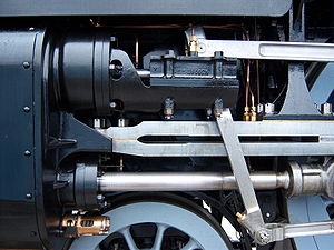
The valve gear of a steam engine is the mechanism that operates the inlet and exhaust valves to admit steam into the cylinder and allow exhaust steam to escape, respectively, at the correct points in the cycle. It can also serve as a reversing gear. It is sometimes referred to as the "motion".

<span class="mw-page-title-main">Walschaerts valve gear</span> Type of valve gear

The Walschaerts valve gear is a type of valve gear used to regulate the flow of steam to the pistons in steam locomotives, invented by Belgian railway engineer Egide Walschaerts in 1844. The gear is sometimes named without the final "s", since it was incorrectly patented under that name. It was extensively used in steam locomotives from the late 19th century until the end of the steam era.

<span class="mw-page-title-main">MR 0-10-0 Lickey Banker</span>

In 1919, the Midland Railway built a single 0-10-0 steam locomotive, No 2290. It was designed by James Anderson for banking duties on the Lickey Incline in Worcestershire, England. It became known as "Big Bertha" or "Big Emma" by railwaymen and railway enthusiasts.

<span class="mw-page-title-main">GWR 4100 Class</span> Class of 84 British 4–4-0 locomotives

The GWR 4100 Class was a class of steam locomotives in the Great Western Railway (GWR) of the United Kingdom.

The Great Western Railway 3800 Class, also known as the County Class, were a class of 4-4-0 steam locomotives for express passenger train work introduced in 1904 in a batch of ten. Two more batches followed in 1906 and 1912 with minor differences. They were designed by George Jackson Churchward, who used standard components to produce a four-coupled version of his Saint Class 4-6-0s.

<span class="mw-page-title-main">Gresley conjugated valve gear</span> Type of mechanism for controlling steam flow in a reciprocating steam engine

The Gresley conjugated valve gear is a valve gear for steam locomotives designed by Sir Nigel Gresley, chief mechanical engineer of the LNER, assisted by Harold Holcroft. It enables a three-cylinder locomotive to operate with only the two sets of valve gear for the outside cylinders, and derives the valve motion for the inside cylinder from them by means of levers. The gear is sometimes known as the Gresley-Holcroft gear, acknowledging Holcroft's major contributions to its development.

<span class="mw-page-title-main">Stephenson valve gear</span> Simple design of valve gear

The Stephenson valve gear or Stephenson link or shifting link is a simple design of valve gear that was widely used throughout the world for various kinds of steam engines. It is named after Robert Stephenson but was invented by his employees.

<span class="mw-page-title-main">Charles Collett</span>

Charles Benjamin Collett was Chief Mechanical Engineer of the Great Western Railway from 1922 to 1941. He designed the GWR's 4-6-0 Castle and King Class express passenger locomotives.

Edward Thompson was an English railway engineer, and was Chief Mechanical Engineer of the London and North Eastern Railway between 1941 and 1946. Edward Thompson was born at Marlborough, Wiltshire on 25 June 1881. He was the son of an assistant master at Marlborough College. He was educated at Marlborough before taking the Mechanical Science Tripos at Pembroke College, Cambridge, earning a third class degree. Thompson's academic background contrasts with that of his predecessor Nigel Gresley, who had also attended Marlborough, but then gained practical experience as a pupil at Horwich Works.

Henry Greenly (1876–1947) was amongst the foremost miniature railway engineers of the 20th century, remembered as a master of engineering design.

<span class="mw-page-title-main">SECR N1 class</span> Class of 6 three-cylinder 2-6-0 locomotives

The SECR N1 class was a type of 3-cylinder 2-6-0 ('mogul') steam locomotive designed by Richard Maunsell for mixed traffic duties, initially on the South Eastern and Chatham Railway (SECR), and later operated for the Southern Railway (SR). The N1 was a development of the basic principles established by the Great Western Railway's (GWR) Chief Mechanical Engineer (CME) George Jackson Churchward and by Maunsell's previous N class design.

<span class="mw-page-title-main">Bulleid chain-driven valve gear</span> Steam locomotive component

The Bulleid chain-driven valve gear is a type of steam locomotive valve gear designed by Oliver Bulleid during the Second World War for use on his Pacific (4-6-2) designs. It was peculiar to the Southern Railway in Britain, and borrowed from motor-vehicle practice in an attempt to create a compact and efficient design with a minimum of service requirements.

<span class="mw-page-title-main">LNWR 2-2-2 3020 Cornwall</span>

London and North Western Railway (LNWR) 2-2-2 No. 3020 Cornwall is a preserved steam locomotive. She was built as a 4-2-2 at Crewe Works in 1847, but was extensively rebuilt and converted into her current form in 1858.

A compound locomotive is a steam locomotive which is powered by a compound engine, a type of steam engine where steam is expanded in two or more stages. The locomotive was only one application of compounding. Two and three stages were used in ships, for example.

Lillian "Curly" Lawrence, known as LBSC, was one of Britain's most prolific and well known model or scale-steam-locomotive designers. LBSC were the initials of Britain's London, Brighton and South Coast Railway, where he was once employed as a fireman.

<span class="mw-page-title-main">South African Class 10B 4-6-2</span>

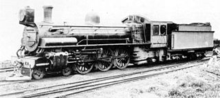
The South African Railways Class 10B 4-6-2 of 1910 was a steam locomotive from the pre-Union era in Transvaal.

<span class="mw-page-title-main">Steam motor</span>

A steam motor is a form of steam engine used for light locomotives and light self-propelled motor cars used on railways. The origins of steam motor cars for railways go back to at least the 1850s, if not earlier, as experimental economizations for railways or railroads with marginal budgets. These first examples, at least in North America, appear to have been fitted with light reciprocating engines, and either direct or geared drives, or geared-endless chain drives. Most incorporated a passenger carrying coach attached to the engine and its boiler. Boiler types varied in these earlier examples, with vertical boilers dominant in the first decade and then with very small diameter horizontal boilers. Other examples of steam motor cars incorporated an express-baggage or luggage type car body, with coupling apparatus provided to allow the steam motor car to draw a light passenger coach.

<span class="mw-page-title-main">CSAR Rack 4-6-4RT</span>

The Central South African Railways Rack 4-6-4RT of 1905 was a South African steam locomotive from the pre-Union era in Transvaal Colony.

GCR Class 9P was a design of four-cylinder steam locomotive of the 4-6-0 wheel arrangement built for hauling express passenger trains on the Great Central Railway in England. A total of six were built: one in 1917, and five in 1920. They were sometimes known as the Lord Faringdon class, from the name of the first one built.

References

  1. "The Engineering and History of Rocket, a survey report", Michael R Bailey and John P Glithero, National Railway Museum 2000, ISBN   1 900747 18 9, Drawing 4.37
  2. 1941 Locomotive Cyclopedia of American Practice, Eleventh Edition, Simmons-Boardman Publishing Corporation, p. 667
  3. Self, Douglas (27 May 2003). "The Nielson One-Cylinder Locomotive" . Retrieved 2 December 2010.