Related Research Articles
An actuator is a component of a machine that produces force, torque, or displacement, when an electrical, pneumatic or hydraulic input is supplied to it in a system. The effect is usually produced in a controlled way. An actuator translates such an input signal into the required form of mechanical energy. It is a type of transducer. In simple terms, it is a "mover".

A synchronous electric motor is an AC electric motor in which, at steady state, the rotation of the shaft is synchronized with the frequency of the supply current; the rotation period is exactly equal to an integer number of AC cycles. Synchronous motors use electromagnets as the stator of the motor which create a magnetic field that rotates in time with the oscillations of the current. The rotor with permanent magnets or electromagnets turns in step with the stator field at the same rate and as a result, provides the second synchronized rotating magnet field. Doubly fed synchronous motors use independently-excited multiphase AC electromagnets for both rotor and stator.

A brushless DC electric motor (BLDC), also known as an electronically commutated motor, is a synchronous motor using a direct current (DC) electric power supply. It uses an electronic controller to switch DC currents to the motor windings producing magnetic fields that effectively rotate in space and which the permanent magnet rotor follows. The controller adjusts the phase and amplitude of the current pulses that control the speed and torque of the motor. It is an improvement on the mechanical commutator (brushes) used in many conventional electric motors.
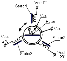
A synchro is, in effect, a transformer whose primary-to-secondary coupling may be varied by physically changing the relative orientation of the two windings. Synchros are often used for measuring the angle of a rotating machine such as an antenna platform or transmitting rotation. In its general physical construction, it is much like an electric motor. The primary winding of the transformer, fixed to the rotor, is excited by an alternating current, which by electromagnetic induction causes voltages to appear between the Y-connected secondary windings fixed at 120 degrees to each other on the stator. The voltages are measured and used to determine the angle of the rotor relative to the stator.
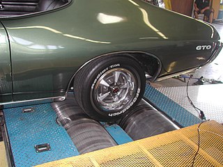
A dynamometer or "dyno" is a device for simultaneously measuring the torque and rotational speed (RPM) of an engine, motor or other rotating prime mover so that its instantaneous power may be calculated, and usually displayed by the dynamometer itself as kW or bhp.

A drive shaft, driveshaft, driving shaft, tailshaft, propeller shaft, or Cardan shaft is a component for transmitting mechanical power, torque, and rotation, usually used to connect other components of a drivetrain that cannot be connected directly because of distance or the need to allow for relative movement between them.
Hybrid Synergy Drive (HSD), also known as Toyota Hybrid System II, is the brand name of Toyota Motor Corporation for the hybrid car drive train technology used in vehicles with the Toyota and Lexus marques. First introduced on the Prius, the technology is an option on several other Toyota and Lexus vehicles and has been adapted for the electric drive system of the hydrogen-powered Mirai, and for a plug-in hybrid version of the Prius. Previously, Toyota also licensed its HSD technology to Nissan for use in its Nissan Altima Hybrid. Its parts supplier Aisin offers similar hybrid transmissions to other car companies.

A motor drive is a physical system that includes a motor. An adjustable speed motor drive is a system that includes a motor that has multiple operating speeds. A variable speed motor drive is a system that includes a motor that is continuously variable in speed. If the motor is generating electrical energy rather than using it, the motor drive could be called a generator drive but is often still referred to as a motor drive.
Engine balance refers to how the inertial forces produced by moving parts in an internal combustion engine or steam engine are neutralised with counterweights and balance shafts, to prevent unpleasant and potentially damaging vibration. The strongest inertial forces occur at crankshaft speed and balance is mandatory, while forces at twice crankshaft speed can become significant in some cases.

A swashplate, also known as slant disk, is a mechanical engineering device used to translate the motion of a rotating shaft into reciprocating motion, or vice versa. The working principle is similar to crankshaft, Scotch yoke, or wobble, nutator, and Z-crank drives in engine designs. It was originally invented to replace a crankshaft, and is one of the most popular concepts used in crankless engines. It was invented by Anthony Michell in 1917.

The rotor is a moving component of an electromagnetic system in the electric motor, electric generator, or alternator. Its rotation is due to the interaction between the windings and magnetic fields which produces a torque around the rotor's axis.
In electrical engineering, electric machine is a general term for machines using electromagnetic forces, such as electric motors, electric generators, and others. They are electromechanical energy converters: an electric motor converts electricity to mechanical power while an electric generator converts mechanical power to electricity. The moving parts in a machine can be rotating or linear. While transformers are occasionally called "static electric machines", since they do not have moving parts, generally they are not considered "machines", but as electrical devices "closely related" to the electrical machines.

A harmonic damper is a device fitted to the free end of the crankshaft of an internal combustion engine to counter torsional and resonance vibrations from the crankshaft. This device must be an interference fit to the crankshaft in order to operate in an effective manner. An interference fit ensures the device moves in perfect step with the crankshaft. It is essential on engines with long crankshafts and V8 engines with cross plane cranks, or V6 and straight-three engines with uneven firing order. Harmonics and torsional vibrations can greatly reduce crankshaft life, or cause instantaneous failure if the crankshaft runs at or through an amplified resonance. Dampers are designed with a specific weight (mass) and diameter, which are dependent on the damping material/method used, to reduce mechanical Q factor, or damp, crankshaft resonances.
On maritime vessels, noise and vibration are not the same but they have the same origin and come in many forms. The methods to handle the related problems are similar, to a certain level, where most shipboard noise problems are reduced by controlling vibration.
The Geislinger coupling is an all-metal coupling for rotating shafts. It is elastic in torsion, allowing it to absorb torsional vibration.

A centrifugal pendulum absorber is a type of tuned mass damper. It reduces the amplitude of a torsional vibration in drive trains that use a combustion engine.

A drivetrain or transmission system, is the group of components that deliver mechanical power from the prime mover to the driven components. In automotive engineering, the drivetrain is the components of a motor vehicle that deliver power to the drive wheels. This excludes the engine or motor that generates the power. In marine applications, the drive shaft will drive a propeller, thruster, or waterjet rather than a drive axle, while the actual engine might be similar to an automotive engine. Other machinery, equipment and vehicles may also use a drivetrain to deliver power from the engine(s) to the driven components.
Electromagnetically induced acoustic noise, electromagnetically excited acoustic noise, or more commonly known as coil whine, is audible sound directly produced by materials vibrating under the excitation of electromagnetic forces. Some examples of this noise include the mains hum, hum of transformers, the whine of some rotating electric machines, or the buzz of fluorescent lamps. The hissing of high voltage transmission lines is due to corona discharge, not magnetism.
This glossary of automotive terms is a list of definitions of terms and concepts related to automobiles, including their parts, operation, and manufacture, as well as automotive engineering, auto repair, and the automotive industry in general. For more specific terminology regarding the design and classification of various automobile styles, see Glossary of automotive design; for terms related to transportation by road, see Glossary of road transport terms; for competitive auto racing, see Glossary of motorsport terms.
References
- ↑ Den Hartog, J. P. (1985). Mechanical Vibrations. Nineola, N.Y.: Dover Publications. p. 174. ISBN 0-486-64785-4.
- ↑ Feese, Hill. "Prevention of Torsional Vibration Problems in Reciprocating Machinery" (PDF). Engineering Dynamics Incorporated. Archived from the original (PDF) on 19 October 2013. Retrieved 17 October 2013.
- ↑ VULKAN Couplings System Competence - Torsional Vibration Calculation, archived from the original on 2021-12-22, retrieved 2021-06-06
- ↑ B. F. Evans, A. J. Smalley, H. R. Simmons, Startup of synchronous motor drive trains: the application of transient torsional analysis of cumulative fatigue assessment, ASME Paper, 85-DET-122, 1985.
- ↑ A. Laschet A., Simulation von Antriebssystemen, Springer-Verlag, Berlin, Heidelberg, London, New-York, Paris, Tokio, 1988.
- ↑ P. Schwibinger, R. Nordmann, Improvement of a reduced torsional model by means of parameter identification, Transactions of the ASME, Journal of Vibration, Acoustics, Stress and Reliability in Design, 111, 1989, pp. 17-26.
- ↑ A. Laschet A., Simulation von Antriebssystemen, Springer-Verlag, Berlin, Heidelberg, London, New-York, Paris, Tokio, 1988.
- ↑ L. Harnefors, Analysis of subsynchronous torsional interaction with power electronic converters, IEEE Transactions on power systems, Vol. 22, No. 1, 2007, pp. 305-313.
- ↑ R. Bogacz, T. Szolc, H. Irretier, An application of torsional wave analysis to turbogenerator rotor shaft response, J.Vibr. Acou. -Trans. of the Asme, Vol. 114-2 (1992) 149-153.
- ↑ O. Ahmedov, V. Zeman, M. Byrtus, Modelling of vibration and modal properties of electric locomotive drive, Eng. Mech., Vol. 19: 2/3 (2012) 165–176.
- ↑ S. Noga, R. Bogacz, T. Markowski, Vibration analysis of a wheel composed of a ring and a wheel-plate modelled as a three-parameter elastic foundation, J.Sound Vib., Vol. 333:24, (2014) 6706-6722.
- ↑ R. Bogacz, R. Konowrocki, On new effects of wheel-rail interaction, Arch. Appl. Mech, Vol.82 (2012)1313-1323.
- ↑ 5. V. Zeman, Z. Hlavac, Dynamic wheelset drive load of the railway vehicle caused by shortcircuit motor moment, App. & Comp. Mech., Vol.3, No.2 (2009)423–434.
- ↑ B.S. Branislav, Simulation of torsion moment at the wheel set of the railway vehicle with the traction electromotor for wavy direct current, Mech. Trans. Com., Issue 3 (2008) 6-9
- ↑ J. Liu, H. Zhao, W. Zhai, Mechanism of self-excited torsional vibration of locomotive driving system, Front. Mech. Eng.China, Vol.5:4 (2010,) 465-469.
- ↑ Szolc T., Konowrocki R., Michajłow M., Pręgowska A., An investigation of the dynamic electromechanical coupling effects in machine drive systems driven by asynchronous motors, Mechanical Systems and Signal Processing, ISSN 0888-3270, Vol.49, pp.118-134, 2014
- ↑ Konowrocki R., Szolc T., Pochanke A., Pręgowska A., An influence of the stepping motor control and friction models on precise positioning of the complex mechanical system, Mechanical Systems and Signal Processing, ISSN 0888-3270, doi : 10.1016/j.ymssp.2015.09.030, Vol.70-71, pp.397-413, 2016
- ↑ Konowrocki R., Szolc T., An analysis of the self-excited torsional vibrations of the electromechanical drive system, Vibrations in Physical Systems, ISSN 0860-6897, Vol.27, pp.187-194, 2016
- ↑ Konowrocki R., Analysis of electromechanical interaction in an electric drive system used in the high speed trains, ART Conference 2016, ADVANCED RAIL TECHNOLOGIES - 5th International Conference, 2016-11-09/11-11, Warsaw (PL), pp.1-2, 2016
- ↑ SoftInWay
- ↑ Rotor Bearing Technology & Software, Inc.
- ↑ Heeringa, T (2018-10-03). "Torsional Vibration Analysis by Bondgraph Modelling. A practical approach". Proceedings of the International Naval Engineering Conference and Exhibition (INEC). Vol. 14. Glasgow, UK. doi: 10.24868/issn.2515-818X.2018.034 .
{{cite book}}: CS1 maint: location missing publisher (link)