| Bulkhead gates are vertical walls with movable, or re-movable, sections. Movable sections can be lifted to allow water to pass underneath (as in a sluice gate) and over the top of the structure. Historically, these gates used stacked timbers known as stoplogs or wooden panels known as flashboards to set the dam's crest height. Some floodgates known as coupures in large levee systems slide sideways to open for various traffic. Bulkhead gates can also be made of other materials and used as a single bulkhead unit. Miter gates are used in ship locks and usually close at an 18° angle to approximate an arch. |  A sluice gate on the Harran canal |  A flood wall gate at Harlan, Kentucky |
Hinged crest gates, are wall sections that rotate from vertical to horizontal, thereby varying the height of the dam. They are generally controlled with hydraulic power, although some are passive and are powered by the water being impounded. Variations: - flap gate
- fish-belly flap gates
- Bascule gates
- Pelican gates
| 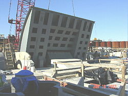 A US Army Corps of Engineers hinged bascule crest gate during installation |  Fish belly flap gates at the Scrivener Dam, Canberra |
| Radial gates are rotary gates consisting of cylindrical sections. They may rotate vertically or horizontally. Tainter gates are a vertical design that rotates up to allow water to pass underneath. Low friction trunnion bearings, along with a face shape that balances hydrostatic forces, allow this design to close under its own weight as a safety feature. |  Tainter gate diagram |  Tainter gates and spillway |
| Drum gates are hollow gate sections that float on water. They are pinned to rotate up or down. Water is allowed into or out of the flotation chamber to adjust the dam's crest height. |  Drum gates are controlled with valves |  Drum gates on a diversion dam |
- Roller gates are large cylinders that move in an angled slot. They are hoisted with a chain and have a cogged design that interfaces with their slot.
- Clamshell gates have an external clamshell leaf design.
|  A roller gate on the Mississippi | 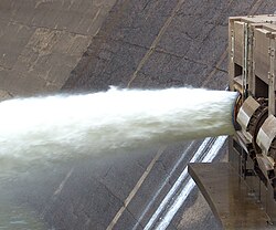 Clamshell floodgates at the Arrowrock Dam. |
| Fusegates are a mechanism designed to provide the controlled release of water in the event of exceptionally large floods. The design consists of free standing blocks (the fusegates) set side by side on a flattened spillway sill. The Fusegate blocks act as a fixed weir most of the time, but in excessive flood conditions they are designed to topple forward, allowing the controlled discharge of water. Multiple fusegates are generally set up side by side, with each fusegate designed to release under progressively extreme flooding, thus minimizing the impact of the floodwater on the river downstream. [1] The system was invented and patented by François Lempérière [2] for Hydroplus (Paris, France), subsidiary of GTM Entrepose. It has been installed on more than 50 dams around the world with sizes ranging from 1 m to more than 9 m in height. Fusegate are typically used to increase the storage capacity of existing dams or to maximize the discharge potential of undersized spillways. |  Typical fusegate sketch |  Fusegate in Terminus Dam - Lake Kaweah |
| Mitre gates |


