
Computer-aided design (CAD) is the use of computers to aid in the creation, modification, analysis, or optimization of a design. This software is used to increase the productivity of the designer, improve the quality of design, improve communications through documentation, and to create a database for manufacturing. Designs made through CAD software help protect products and inventions when used in patent applications. CAD output is often in the form of electronic files for print, machining, or other manufacturing operations. The terms computer-aided drafting (CAD) and computer-aided design and drafting (CADD) are also used.
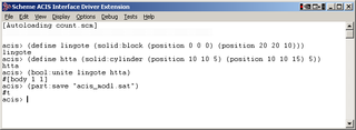
The 3D ACIS Modeler (ACIS) is a geometric modeling kernel developed by Spatial Corporation, part of Dassault Systemes. ACIS is used by many software developers in industries such as computer-aided design (CAD), computer-aided manufacturing (CAM), computer-aided engineering (CAE), architecture, engineering and construction (AEC), coordinate-measuring machine (CMM), 3D animation, and shipbuilding. ACIS provides software developers and manufacturers the underlying 3D modeling functionality.

Technical drawing, drafting or drawing, is the act and discipline of composing drawings that visually communicate how something functions or is constructed.

SolidWorks is a brand within Dassault Systèmes that develops and markets solid modeling computer-aided design, computer-aided engineering, 3D CAD design and collaboration, analysis, and product data management software.

Moulding, or molding, also coving, is a strip of material with various profiles used to cover transitions between surfaces or for decoration. It is traditionally made from solid milled wood or plaster, but may be of plastic or reformed wood. In classical architecture and sculpture, the moulding is often carved in marble or other stones. In historic architecture, and some expensive modern buildings, it may be formed in place with plaster.

A chamfer is a transitional edge between two faces of an object. Sometimes defined as a form of bevel, it is often created at a 45° angle between two adjoining right-angled faces.

A bevelled edge (UK) or beveled edge (US) is an edge of a structure that is not perpendicular to the faces of the piece. The words bevel and chamfer overlap in usage; in general usage they are often interchanged, while in technical usage they may sometimes be differentiated as shown in the image at right. A bevel is typically used to soften the edge of a piece for the sake of safety, wear resistance, or aesthetics; or to facilitate mating with another piece.
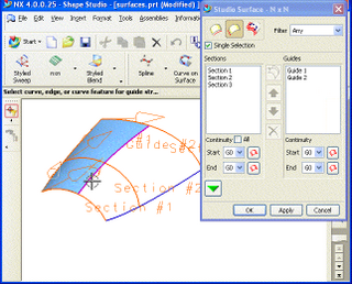
Freeform surface modelling is a technique for engineering freeform surfaces with a CAD or CAID system.

A rectilinear polygon is a polygon all of whose sides meet at right angles. Thus the interior angle at each vertex is either 90° or 270°. Rectilinear polygons are a special case of isothetic polygons.

Daxcon Engineering, Inc., is a company headquartered in Bartonville, Illinois, that provides engineering and manufacturing consultation to the Defense & Aerospace, Mining & Construction, Automotive, Consumer Products, and Agriculture industries. On 15 January 2010, it was acquired by Infotech Enterprises America Inc., which is now a wholly owned subsidiary of Cyient, a firm in India.

Butt welding is when two pieces of metal are placed end-to-end without overlap and then welded along the joint. Importantly, in a butt joint, the surfaces of the workpieces being joined are on the same plane and the weld metal remains within the planes of the surfaces.

Claris CAD was a two-dimensional computer-aided design program for Apple Inc. Macintosh.
The term "feature" implies different meanings in different engineering disciplines. This has resulted in many ambiguous definitions for feature. A feature, in computer-aided design (CAD), usually refers to a region of a part with some interesting geometric or topological properties. These are more precisely called form features. Form features contain both shape information and parametric information of a region of interest. They are now ubiquitous in most current CAD software, where they are used as the primary means of creating 3D geometric models. Examples of form features are extruded boss, loft, etc. Form feature is not the only type of feature that is discussed in CAD literature. Sometimes a part's functional or manufacturing features of the subject of attention. Although it is quite possible to see form features and manufacturing features are called by the same name, they are not exactly the same concepts. For example, one may either use the name "pocket" to refer to a swept cut on the boundary of a part model, or to refer to a trace left on the part boundary by a specific machining operation. The former is exclusively concerned with a geometric shape whereas the latter is concerned with both the geometric shape and a manufacturing operation, needing more parameters in its definition. As such, a manufacturing feature can be minimally defined as a form feature, but not necessarily vice versa. Machining features are an important subset of manufacturing features. A machining feature can be regarded as the volume swept by a "cutting" tool, which is always a negative (subtracted) volume. Finally, there is also the concept of assembly feature, which encodes the assembly method between connected components.

In engineering, a boss is a protruding feature on a workpiece. A common use for a boss is to locate one object within a pocket or hole of another object. For instance, some motors use a precisely machined boss on the front face to locate it on the mating part. Like a process on a bone, bosses on castings can provide attachment points or bearing surfaces.

A computer numerical control (CNC) router is a computer-controlled cutting machine which typically mounts a hand-held router as a spindle which is used for cutting various materials, such as wood, composites, metals, plastics, glass, and foams. CNC routers can perform the tasks of many carpentry shop machines such as the panel saw, the spindle moulder, and the boring machine. They can also cut joinery such as mortises and tenons.

WorkNC is a computer-aided manufacturing (CAM) software developed by Sescoi for multi-axis machining.
SpaceClaim is a solid modeling CAD software that runs on Microsoft Windows and developed by SpaceClaim Corporation. The company is headquartered in Concord, Massachusetts.

SolveSpace is a free and open-source 2D/3D constraint-based parametric computer-aided design (CAD) software that supports basic 2D and 3D constructive solid geometry modeling.

Fillet welding refers to the process of joining two pieces of metal together when they are perpendicular or at an angle. These welds are commonly referred to as tee joints, which are two pieces of metal perpendicular to each other, or lap joints, which are two pieces of metal that overlap and are welded at the edges. The weld is triangular in shape and may have a concave, flat or convex surface depending on the welder's technique. Welders use fillet welds when connecting flanges to pipes and welding cross sections of infrastructure, and when bolts are not strong enough and will wear off easily.
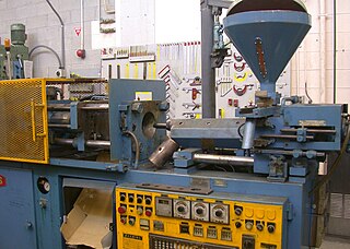
Injection molding has been one of the most popular ways for fabricating plastic parts for a very long time. They are used in automotive interior parts, electronic housings, housewares, medical equipment, compact discs, and even doghouses. Below are certain rule based standard guidelines which can be referred to while designing parts for injection molding considering manufacturability in mind.

