In solid mechanics, a stress concentration (also called a stress raiser or a stress riser or notch sensitivity) is a location in an object where the stress is significantly greater than the surrounding region. Stress concentrations occur when there are irregularities in the geometry or material of a structural component that cause an interruption to the flow of stress. This arises from such details as holes, grooves, notches and fillets. Stress concentrations may also occur from accidental damage such as nicks and scratches.
The degree of concentration of a discontinuity under typically tensile loads can be expressed as a non-dimensional stress concentration factor, which is the ratio of the highest stress to the nominal far field stress. For a circular hole in an infinite plate, .[1] The stress concentration factor should not be confused with the stress intensity factor, which is used to define the effect of a crack on the stresses in the region around a crack tip.[2]
For ductile materials, large loads can cause localised plastic deformation or yielding that will typically occur first at a stress concentration allowing a redistribution of stress and enabling the component to continue to carry load. Brittle materials will typically fail at the stress concentration. However, repeated low level loading may cause a fatigue crack to initiate and slowly grow at a stress concentration leading to the failure of even ductile materials. Fatigue cracks always start at stress raisers, so removing such defects increases the fatigue strength.
Description
Stress concentrations occur when there are irregularities in the geometry or material of a structural component that cause an interruption to the flow of stress.
Geometric discontinuities cause an object to experience a localised increase in stress. Examples of shapes that cause stress concentrations are sharp internal corners, holes, and sudden changes in the cross-sectional area of the object as well as unintentional damage such as nicks, scratches and cracks. High local stresses can cause objects to fail more quickly, so engineers typically design the geometry to minimize stress concentrations.
Material discontinuities, such as inclusions in metals, may also concentrate the stress. Inclusions on the surface of a component may be broken from machining during manufacture leading to microcracks that grow in service from cyclic loading. Internally, the failure of the interfaces around inclusions during loading may lead to static failure by microvoid coalescence.
Stress concentration factor
The stress concentration factor, , is the ratio of the highest stress to a nominal stress of the gross cross-section and defined as[3]
Note that the dimensionless stress concentration factor is a function of the geometry shape and independent of its size.[4] These factors can be found in typical engineering reference materials.
Stress concentration around an elliptical hole in a plate in tension
E. Kirsch derived the equations for the elastic stress distribution around a hole. The maximum stress felt near a hole or notch occurs in the area of lowest radius of curvature. In an elliptical hole of length and width , under a far-field stress , the stress at the ends of the major axes is given by Inglis' equation:[5]
where is the radius of curvature of the elliptical hole. For circular holes in an infinite plate where , the stress concentration factor is .
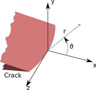
As the radius of curvature approaches zero, such as at the tip of a sharp crack, the maximum stress approaches infinity and a stress concentration factor cannot therefore be used for a crack. Instead, the stress intensity factor which defines the scaling of the stress field around a crack tip, is used.[2]
Causes of Stress Concentration
Stress concentration can arise due to various factors. The following are the main causes of stress concentration:
Material Defects: When designing mechanical components, it is generally presumed that the material used is consistent and homogeneous throughout. In practice, however, material inconsistencies such as internal cracks, blowholes, cavities in welds, air holes in metal parts, and non-metallic or foreign inclusions can occur. These defects act as discontinuities within the component, disrupting the uniform distribution of stress and thereby leading to stress concentration.
Contact Stress: Mechanical components are frequently subjected to forces that are concentrated at specific points or small areas. This localized application of force can result in disproportionately high pressures at these points, causing stress concentration. Typical instances include the interactions at the points of contact in meshing gear teeth,[6] the interfaces between cams and followers, and the contact zones in ball bearings.
Thermal Stress: Thermal stress occurs when different parts of a structure expand or contract at different rates due to variations in temperature. This differential in thermal expansion and contraction generates internal stresses, which can lead to areas of stress concentration within the structure.
Geometric Discontinuities: Features such as steps on a shaft, shoulders, and other abrupt changes in the cross-sectional area of components are often necessary for mounting elements like gears and bearings or for assembly considerations. While these features are essential for the functionality of the device, they introduce sharp transitions in geometry that become hotspots for stress concentration. Additionally, design elements like oil holes, grooves, keyways, splines, and screw threads also introduce discontinuities that further exacerbate stress concentration.
Rough Surface: Imperfections on the surface of components, such as machining scratches, stamp marks, or inspection marks, can interrupt the smooth flow of stress across the surface, leading to localized increases in stress. These imperfections, although often small, can significantly impact the durability and performance of mechanical components by initiating stress concentration.[7]
Methods for determining factors
There are experimental methods for measuring stress concentration factors including photoelastic stress analysis, thermoelastic stress analysis,[8] brittle coatings or strain gauges.
During the design phase, there are multiple approaches to estimating stress concentration factors. Several catalogs of stress concentration factors have been published.[9] Perhaps most famous is Stress Concentration Design Factors by Peterson, first published in 1953.[10][11]Finite element methods are commonly used in design today. Other methods include the boundary element method[12] and meshfree methods.
Limiting the effects of stress concentrations
Stress concentrations can be mitigated through techniques that smoothen the flow of stress around a discontinuity:
Material Removal: Introducing auxiliary holes in the high stress region to create a more gradual transition. The size and position of these holes must be optimized.[13][14] Known as crack tip blunting, a counter-intuitive example of reducing one of the worst types of stress concentrations, a crack, is to drill a large hole at the end of the crack. The drilled hole, with its relatively large size, serves to increase the effective crack tip radius and thus reduce the stress concentration.[4]
Hole Reinforcement: Adding higher strength material around the hole, usually in the form of bonded rings or doublers.[15] Composite reinforcements can reduce the SCF.
Shape Optimization: Adjusting the hole shape, often transitioning from circular to elliptical, to minimize stress gradients. This must be checked for feasibility. One example is adding a fillet to internal corners.[16] Another example is in a threaded component, where the force flow line is bent as it passes from shank portion to threaded portion; as a result, stress concentration takes place. To reduce this, a small undercut is made between the shank and threaded portions
Functionally Graded Materials: Using materials with properties that vary gradually can reduce the SCF compared to a sudden change in material.
The optimal mitigation technique depends on the specific geometry, loading scenario, and manufacturing constraints. In general, a combination of methods is required for the best result. While there is no universal solution, careful analysis of the stress flow and parameterization of the model can point designers toward an effective stress reduction strategy.
Examples
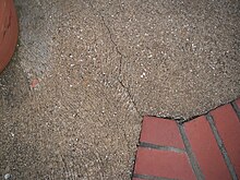
The sharp corner at the brick has acted as a stress concentrator within the concrete causing it to crack
The de Havilland Cometaircraft experienced a number of catastrophic failures that were eventually found to be due to fatigue cracks growing from the high stress concentration caused by the use of punched rivet holes around the windows. The square passenger windows were also found to have higher stress concentrations than expected and were redesigned.
Brittle fractures at the corners of hatches in Liberty ships in cold and stressful conditions in winter storms in the Atlantic Ocean.
A focus point of stress on the margins of an implant, where metal meets bone, of an implantedorthosis is very likely to be the point of failure.
Related Research Articles
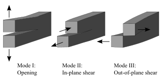
Fracture is the appearance of a crack or complete separation of an object or material into two or more pieces under the action of stress. The fracture of a solid usually occurs due to the development of certain displacement discontinuity surfaces within the solid. If a displacement develops perpendicular to the surface, it is called a normal tensile crack or simply a crack; if a displacement develops tangentially, it is called a shear crack, slip band, or dislocation.
The strength of materials is determined using various methods of calculating the stresses and strains in structural members, such as beams, columns, and shafts. The methods employed to predict the response of a structure under loading and its susceptibility to various failure modes takes into account the properties of the materials such as its yield strength, ultimate strength, Young's modulus, and Poisson's ratio. In addition, the mechanical element's macroscopic properties such as its length, width, thickness, boundary constraints and abrupt changes in geometry such as holes are considered.
In mechanics, compressive strength is the capacity of a material or structure to withstand loads tending to reduce size (compression). It is opposed to tensile strength which withstands loads tending to elongate, resisting tension. In the study of strength of materials, compressive strength, tensile strength, and shear strength can be analyzed independently.
In materials science, fatigue is the initiation and propagation of cracks in a material due to cyclic loading. Once a fatigue crack has initiated, it grows a small amount with each loading cycle, typically producing striations on some parts of the fracture surface. The crack will continue to grow until it reaches a critical size, which occurs when the stress intensity factor of the crack exceeds the fracture toughness of the material, producing rapid propagation and typically complete fracture of the structure.
Stress–strain analysis is an engineering discipline that uses many methods to determine the stresses and strains in materials and structures subjected to forces. In continuum mechanics, stress is a physical quantity that expresses the internal forces that neighboring particles of a continuous material exert on each other, while strain is the measure of the deformation of the material.
Fracture mechanics is the field of mechanics concerned with the study of the propagation of cracks in materials. It uses methods of analytical solid mechanics to calculate the driving force on a crack and those of experimental solid mechanics to characterize the material's resistance to fracture.
Crazing is a yielding mechanism in polymers characterized by the formation of a fine network of microvoids and fibrils. These structures typically appear as linear features and frequently precede brittle fracture. The fundamental difference between crazes and cracks is that crazes contain polymer fibrils, constituting about 50% of their volume, whereas cracks do not. Unlike cracks, crazes can transmit load between their two faces through these fibrils.
In fracture mechanics, the stress intensity factor is used to predict the stress state near the tip of a crack or notch caused by a remote load or residual stresses. It is a theoretical construct usually applied to a homogeneous, linear elastic material and is useful for providing a failure criterion for brittle materials, and is a critical technique in the discipline of damage tolerance. The concept can also be applied to materials that exhibit small-scale yielding at a crack tip.
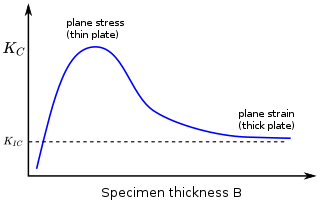
In materials science, fracture toughness is the critical stress intensity factor of a sharp crack where propagation of the crack suddenly becomes rapid and unlimited. A component's thickness affects the constraint conditions at the tip of a crack with thin components having plane stress conditions and thick components having plane strain conditions. Plane strain conditions give the lowest fracture toughness value which is a material property. The critical value of stress intensity factor in mode I loading measured under plane strain conditions is known as the plane strain fracture toughness, denoted . When a test fails to meet the thickness and other test requirements that are in place to ensure plane strain conditions, the fracture toughness value produced is given the designation . Fracture toughness is a quantitative way of expressing a material's resistance to crack propagation and standard values for a given material are generally available.
The three-point bending flexural test provides values for the modulus of elasticity in bending , flexural stress , flexural strain and the flexural stress–strain response of the material. This test is performed on a universal testing machine with a three-point or four-point bend fixture. The main advantage of a three-point flexural test is the ease of the specimen preparation and testing. However, this method has also some disadvantages: the results of the testing method are sensitive to specimen and loading geometry and strain rate.
The J-integral represents a way to calculate the strain energy release rate, or work (energy) per unit fracture surface area, in a material. The theoretical concept of J-integral was developed in 1967 by G. P. Cherepanov and independently in 1968 by James R. Rice, who showed that an energetic contour path integral was independent of the path around a crack.
Paris' law is a crack growth equation that gives the rate of growth of a fatigue crack. The stress intensity factor characterises the load around a crack tip and the rate of crack growth is experimentally shown to be a function of the range of stress intensity seen in a loading cycle. The Paris equation is
A fracture is any separation in a geologic formation, such as a joint or a fault that divides the rock into two or more pieces. A fracture will sometimes form a deep fissure or crevice in the rock. Fractures are commonly caused by stress exceeding the rock strength, causing the rock to lose cohesion along its weakest plane. Fractures can provide permeability for fluid movement, such as water or hydrocarbons. Highly fractured rocks can make good aquifers or hydrocarbon reservoirs, since they may possess both significant permeability and fracture porosity.
Material failure theory is an interdisciplinary field of materials science and solid mechanics which attempts to predict the conditions under which solid materials fail under the action of external loads. The failure of a material is usually classified into brittle failure (fracture) or ductile failure (yield). Depending on the conditions most materials can fail in a brittle or ductile manner or both. However, for most practical situations, a material may be classified as either brittle or ductile.
According to the classical theories of elastic or plastic structures made from a material with non-random strength (ft), the nominal strength (σN) of a structure is independent of the structure size (D) when geometrically similar structures are considered. Any deviation from this property is called the size effect. For example, conventional strength of materials predicts that a large beam and a tiny beam will fail at the same stress if they are made of the same material. In the real world, because of size effects, a larger beam will fail at a lower stress than a smaller beam.
Polymer fracture is the study of the fracture surface of an already failed material to determine the method of crack formation and extension in polymers both fiber reinforced and otherwise. Failure in polymer components can occur at relatively low stress levels, far below the tensile strength because of four major reasons: long term stress or creep rupture, cyclic stresses or fatigue, the presence of structural flaws and stress-cracking agents. Formations of submicroscopic cracks in polymers under load have been studied by x ray scattering techniques and the main regularities of crack formation under different loading conditions have been analyzed. The low strength of polymers compared to theoretically predicted values are mainly due to the many microscopic imperfections found in the material. These defects namely dislocations, crystalline boundaries, amorphous interlayers and block structure can all lead to the non-uniform distribution of mechanical stress.
Crack tip opening displacement (CTOD) or is the distance between the opposite faces of a crack tip at the 90° intercept position. The position behind the crack tip at which the distance is measured is arbitrary but commonly used is the point where two 45° lines, starting at the crack tip, intersect the crack faces. The parameter is used in fracture mechanics to characterize the loading on a crack and can be related to other crack tip loading parameters such as the stress intensity factor and the elastic-plastic J-integral.
A crack growth equation is used for calculating the size of a fatigue crack growing from cyclic loads. The growth of a fatigue crack can result in catastrophic failure, particularly in the case of aircraft. When many growing fatigue cracks interact with one another it is known as widespread fatigue damage. A crack growth equation can be used to ensure safety, both in the design phase and during operation, by predicting the size of cracks. In critical structure, loads can be recorded and used to predict the size of cracks to ensure maintenance or retirement occurs prior to any of the cracks failing. Safety factors are used to reduce the predicted fatigue life to a service fatigue life because of the sensitivity of the fatigue life to the size and shape of crack initiating defects and the variability between assumed loading and actual loading experienced by a component.
Fatigue testing is a specialised form of mechanical testing that is performed by applying cyclic loading to a coupon or structure. These tests are used either to generate fatigue life and crack growth data, identify critical locations or demonstrate the safety of a structure that may be susceptible to fatigue. Fatigue tests are used on a range of components from coupons through to full size test articles such as automobiles and aircraft.
Fastran is a computer program for calculating the rate of fatigue crack growth by combining crack growth equations and a simulation of the plasticity at the crack tip.
↑ Tuplin WA. Gear-Tooth Stresses at High Speed. Proceedings of the Institution of Mechanical Engineers. 1950;163(1):162-175. doi:10.1243/PIME_PROC_1950_163_020_02
↑ Peterson, Rudolf Earl (1953). Stress Concentration Design Factors. John Wiley & Sons. ISBN978-0471683766.
↑ Pilkey, Walter D. (1999). Peterson's Stress Concentration Factors (2nded.). Wiley. ISBN0-471-53849-3.
↑ R. T. Fenner, “The boundary integral equation and boundary element method in engineering stress analysis”, The Journal of Strain Analysis for Engineering Design IMechE, vol. 18, no. 4, pp. 199-205, 1983.
↑ K. Rajaiah and A. J. Durelli, “Optimum hole shapes in finite plates under uni-axial load,” Applied Mechanics, vol. 46(3), pp. 691-695, 1979.
↑ S. A. Meguid, “Finite element analysis of defence hole systems for the reduction of stress Concentration in a uniaxially–loaded plate with coaxial holes,” Engineering Fracture Mechanics, vol. 25, no. 4, pp. 403-413, 1986.
↑ G. S. Giare and R. Shabahang, “The reduction of stress concentration around the hole in an isotropic plate using composite material,” Engineering Fracture Mechanics, vol. 32, no. 5, pp. 757-766, 1989.
↑ Z. Wu, “Optimal hole shape for minimum stress concentration using parameterized geometry models,” Structural and Multidisciplinary Optimization, vol. 37, no. 6, pp. 625-634, Feb, 2009.
This page is based on this Wikipedia article Text is available under the CC BY-SA 4.0 license; additional terms may apply. Images, videos and audio are available under their respective licenses.