
Ductility is a mechanical property commonly described as a material's amenability to drawing. In materials science, ductility is defined by the degree to which a material can sustain plastic deformation under tensile stress before failure. Ductility is an important consideration in engineering and manufacturing. It defines a material's suitability for certain manufacturing operations and its capacity to absorb mechanical overload. Some metals that are generally described as ductile include gold and copper, while platinum is the most ductile of all metals in pure form. However, not all metals experience ductile failure as some can be characterized with brittle failure like cast iron. Polymers generally can be viewed as ductile materials as they typically allow for plastic deformation.

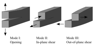
Fracture is the separation of an object or material into two or more pieces under the action of stress. The fracture of a solid usually occurs due to the development of certain displacement discontinuity surfaces within the solid. If a displacement develops perpendicular to the surface, it is called a normal tensile crack or simply a crack; if a displacement develops tangentially, it is called a shear crack, slip band or dislocation.

In materials science, fatigue is the initiation and propagation of cracks in a material due to cyclic loading. Once a fatigue crack has initiated, it grows a small amount with each loading cycle, typically producing striations on some parts of the fracture surface. The crack will continue to grow until it reaches a critical size, which occurs when the stress intensity factor of the crack exceeds the fracture toughness of the material, producing rapid propagation and typically complete fracture of the structure.

In materials science and metallurgy, toughness is the ability of a material to absorb energy and plastically deform without fracturing. Toughness is the strength with which the material opposes rupture. One definition of material toughness is the amount of energy per unit volume that a material can absorb before rupturing. This measure of toughness is different from that used for fracture toughness, which describes load bearing capabilities of materials with flaws. It is also defined as a material's resistance to fracture when stressed.
Fracture mechanics is the field of mechanics concerned with the study of the propagation of cracks in materials. It uses methods of analytical solid mechanics to calculate the driving force on a crack and those of experimental solid mechanics to characterize the material's resistance to fracture.

A material is brittle if, when subjected to stress, it fractures with little elastic deformation and without significant plastic deformation. Brittle materials absorb relatively little energy prior to fracture, even those of high strength. Breaking is often accompanied by a sharp snapping sound.
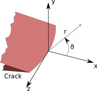
In fracture mechanics, the stress intensity factor is used to predict the stress state near the tip of a crack or notch caused by a remote load or residual stresses. It is a theoretical construct usually applied to a homogeneous, linear elastic material and is useful for providing a failure criterion for brittle materials, and is a critical technique in the discipline of damage tolerance. The concept can also be applied to materials that exhibit small-scale yielding at a crack tip.
In materials science, the Charpy impact test, also known as the Charpy V-notch test, is a standardized high strain rate test which determines the amount of energy absorbed by a material during fracture. Absorbed energy is a measure of the material's notch toughness. It is widely used in industry, since it is easy to prepare and conduct and results can be obtained quickly and cheaply. A disadvantage is that some results are only comparative. The test was pivotal in understanding the fracture problems of ships during World War II.
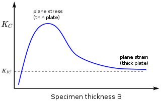
In materials science, fracture toughness is the critical stress intensity factor of a sharp crack where propagation of the crack suddenly becomes rapid and unlimited. A component's thickness affects the constraint conditions at the tip of a crack with thin components having plane stress conditions and thick components having plane strain conditions. Plane strain conditions give the lowest fracture toughness value which is a material property. The critical value of stress intensity factor in mode I loading measured under plane strain conditions is known as the plane strain fracture toughness, denoted . When a test fails to meet the thickness and other test requirements that are in place to ensure plane strain conditions, the fracture toughness value produced is given the designation . Fracture toughness is a quantitative way of expressing a material's resistance to crack propagation and standard values for a given material are generally available.

The Izod impact strength test is an ASTM standard method of determining the impact resistance of materials. A pivoting arm is raised to a specific height and then released. The arm swings down hitting a notched sample, breaking the specimen. The energy absorbed by the sample is calculated from the height the arm swings to after hitting the sample. A notched sample is generally used to determine impact energy and notch sensitivity.

The three-point bending flexural test provides values for the modulus of elasticity in bending , flexural stress , flexural strain and the flexural stress–strain response of the material. This test is performed on a universal testing machine with a three-point or four-point bend fixture. The main advantage of a three-point flexural test is the ease of the specimen preparation and testing. However, this method has also some disadvantages: the results of the testing method are sensitive to specimen and loading geometry and strain rate.
Polymer characterization is the analytical branch of polymer science.

A compact tension specimen (CT) is a type of standard notched specimen in accordance with ASTM and ISO standards. Compact tension specimens are used extensively in the area of fracture mechanics and corrosion testing, in order to establish fracture toughness and fatigue crack growth data for a material.
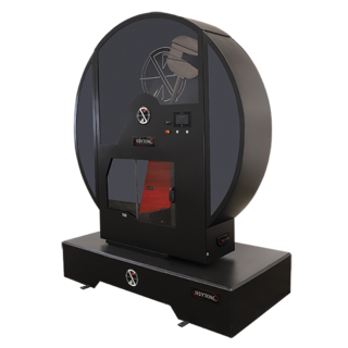
Rising Step Load Testing is a testing system that can apply loads in tension or bending to evaluate hydrogen-induced cracking. It was specifically designed to conduct the accelerated ASTM F1624 step-modified, slow strain rate tests on a variety of test coupons or structural components. It can also function to conduct conventional ASTM E8 tensile tests; ASTM F519 200-hr Sustained Load Tests with subsequent programmable step loads to rupture for increased reliability; and ASTM G129 Slow Strain Rate Tensile tests.
Mechanical testing covers a wide range of tests, which can be divided broadly into two types:
- those that aim to determine a material's mechanical properties, independent of geometry.
- those that determine the response of a structure to a given action, e.g. testing of composite beams, aircraft structures to destruction, etc.
The wafer bond characterization is based on different methods and tests. Considered a high importance of the wafer are the successful bonded wafers without flaws. Those flaws can be caused by void formation in the interface due to unevenness or impurities. The bond connection is characterized for wafer bond development or quality assessment of fabricated wafers and sensors.
Polymer fracture is the study of the fracture surface of an already failed material to determine the method of crack formation and extension in polymers both fiber reinforced and otherwise. Failure in polymer components can occur at relatively low stress levels, far below the tensile strength because of four major reasons: long term stress or creep rupture, cyclic stresses or fatigue, the presence of structural flaws and stress-cracking agents. Formations of submicroscopic cracks in polymers under load have been studied by x ray scattering techniques and the main regularities of crack formation under different loading conditions have been analyzed. The low strength of polymers compared to theoretically predicted values are mainly due to the many microscopic imperfections found in the material. These defects namely dislocations, crystalline boundaries, amorphous interlayers and block structure can all lead to the non-uniform distribution of mechanical stress.

Crack tip opening displacement (CTOD) or is the distance between the opposite faces of a crack tip at the 90° intercept position. The position behind the crack tip at which the distance is measured is arbitrary but commonly used is the point where two 45° lines, starting at the crack tip, intersect the crack faces. The parameter is used in fracture mechanics to characterize the loading on a crack and can be related to other crack tip loading parameters such as the stress intensity factor and the elastic-plastic J-integral.

Fatigue testing is a specialised form of mechanical testing that is performed by applying cyclic loading to a coupon or structure. These tests are used either to generate fatigue life and crack growth data, identify critical locations or demonstrate the safety of a structure that may be susceptible to fatigue. Fatigue tests are used on a range of components from coupons through to full size test articles such as automobiles and aircraft.
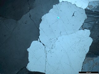
Microcracks in rock, also known as microfractures and cracks, are spaces in rock with the longest length of 1000 μm and the other two dimensions of 10 μm. In general, the ratio of width to length of microcracks is between 10−3 to 10−5.
