Prismatic joint

Last updated
Prismatic joint seen in 2-dimensional form. Only linear motion is possible. In contrast to a revolute joint the axis is prevented from rotating (this can be accomplished by giving the axis a prismatic shape which is not visible here). Prismatic joint.svg
Prismatic joint seen in 2-dimensional form. Only linear motion is possible. In contrast to a revolute joint the axis is prevented from rotating (this can be accomplished by giving the axis a prismatic shape which is not visible here).

A prismatic joint provides a linear sliding movement between two bodies, and is often called a slider, as in the slider-crank linkage. A prismatic pair is also called as sliding pair. A prismatic joint can be formed with a polygonal cross-section to resist rotation. See for example the dovetail joint and linear bearings.

Slider-crank linkage

A slider-crank linkage is a four-link mechanism with three revolute joints and one prismatic, or sliding, joint. The rotation of the crank drives the linear movement the slider, or the expansion of gases against a sliding piston in a cylinder can drive the rotation of the crank.

Dovetail joint joinery technique

A dovetail joint or simply dovetail is a joinery technique most commonly used in woodworking joinery (carpentry) including furniture, cabinets. log buildings and traditional timber framing. Noted for its resistance to being pulled apart, the dovetail joint is commonly used to join the sides of a drawer to the front. A series of 'pins' cut to extend from the end of one board interlock with a series of 'tails' cut into the end of another board. The pins and tails have a trapezoidal shape. Once glued, a wooden dovetail joint requires no mechanical fasteners.

The relative position of two bodies connected by a prismatic joint is defined by the amount of linear slide of one relative to the other one. This one parameter movement identifies this joint as a one degree of freedom kinematic pair. [1]

In physics, the degree of freedom (DOF) of a mechanical system is the number of independent parameters that define its configuration. It is the number of parameters that determine the state of a physical system and is important to the analysis of systems of bodies in mechanical engineering, aeronautical engineering, robotics, and structural engineering.

A kinematic pair is a connection between two physical objects that imposes constraints on their relative movement. Franz Reuleaux introduced the kinematic pair as a new approach to the study of machines that provided an advance over the motion of elements consisting of simple machines.

Prismatic joints provide single-axis sliding often found in hydraulic and pneumatic cylinders. [2]

Hydraulic cylinder

A hydraulic cylinder is a mechanical actuator that is used to give a unidirectional force through a unidirectional stroke. It has many applications, notably in construction equipment, manufacturing machinery, and civil engineering.

Pneumatic cylinder

Pneumatic cylinder(s) are mechanical devices which use the power of compressed gas to produce a force in a reciprocating linear motion.

See also

Cylindrical joint

A cylindrical joint is a two-degrees-of-freedom kinematic pair used in mechanisms. Cylindrical joints provide single-axis sliding function as well as a single axis rotation, providing a way for two rigid bodies to translate and rotate freely. This can be pictured by an unsecured axle mounted on a chassis, as it may freely rotate and translate.

Kinematics is a branch of classical mechanics that describes the motion of points, bodies (objects), and systems of bodies without considering the forces that cause them to move. Kinematics, as a field of study, is often referred to as the "geometry of motion" and is occasionally seen as a branch of mathematics. A kinematics problem begins by describing the geometry of the system and declaring the initial conditions of any known values of position, velocity and/or acceleration of points within the system. Then, using arguments from geometry, the position, velocity and acceleration of any unknown parts of the system can be determined. The study of how forces act on bodies falls within kinetics, not kinematics. For further details, see analytical dynamics.

A mechanical joint is a section of a machine which is used to connect one or more mechanical part to another. Mechanical joints may be temporary or permanent, most types are designed to be disassembled. Most mechanical joints are designed to allow relative movement of these mechanical parts of the machine in one degree of freedom, and restrict movement in one or more others. Mechanical joints are much cheaper and are usually bought ready assembled.

Related Research Articles

Machine tool using energy to perform an intended action

A machine is a mechanical structure that uses power to apply forces and control movement to perform an intended action. Machines can be driven by animals and people, by natural forces such as wind and water, and by chemical, thermal, or electrical power, and include a system of mechanisms that shape the actuator input to achieve a specific application of output forces and movement. They can also include computers and sensors that monitor performance and plan movement, often called mechanical systems.

Four-bar linkage

A four-bar linkage, also called a four-bar, is the simplest movable closed-chain linkage. It consists of four bodies, called bars or links, connected in a loop by four joints. Generally, the joints are configured so the links move in parallel planes, and the assembly is called a planar four-bar linkage. Spherical and spatial four-bar linkages also exist and are used in practice.

Linkage (mechanical) assembly of bodies connected to manage forces and movement

A mechanical linkage is an assembly of bodies connected to manage forces and movement. The movement of a body, or link, is studied using geometry so the link is considered to be rigid. The connections between links are modeled as providing ideal movement, pure rotation or sliding for example, and are called joints. A linkage modeled as a network of rigid links and ideal joints is called a kinematic chain.

Mirror mount

A mirror mount is a device that holds a mirror. In optics research, these can be quite sophisticated devices, due to the need to be able to tip and tilt the mirror by controlled amounts, while still holding it in a precise position when it is not being adjusted.

Parallel manipulator

A parallel manipulator is a mechanical system that uses several computer-controlled serial chains to support a single platform, or end-effector. Perhaps, the best known parallel manipulator is formed from six linear actuators that support a movable base for devices such as flight simulators. This device is called a Stewart platform or the Gough-Stewart platform in recognition of the engineers who first designed and used them.

Multibody system is the study of the dynamic behavior of interconnected rigid or flexible bodies, each of which may undergo large translational and rotational displacements.

Kinematic diagram graph showing machines as links and joints

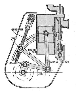
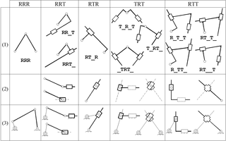
A kinematic diagram or kinematic scheme illustrates the connectivity of links and joints of a mechanism or machine rather than the dimensions or shape of the parts. Often links are presented as geometric objects, such as lines, triangles or squares, that support schematic versions of the joints of the mechanism or machine. A kinematic diagram is sometimes called a joint map or a skeleton diagram.

Kinematic chain assembly of rigid bodies connected by joints to provide constrained motion that is the mathematical model for a mechanical system

In mechanical engineering, a kinematic chain is an assembly of rigid bodies connected by joints to provide constrained motion that is the mathematical model for a mechanical system. As in the familiar use of the word chain, the rigid bodies, or links, are constrained by their connections to other links. An example is the simple open chain formed by links connected in series, like the usual chain, which is the kinematic model for a typical robot manipulator.

Robotic arm type of mechanical arm with similar functions to a human arm

A robotic arm is a type of mechanical arm, usually programmable, with similar functions to a human arm; the arm may be the sum total of the mechanism or may be part of a more complex robot. The links of such a manipulator are connected by joints allowing either rotational motion or translational (linear) displacement. The links of the manipulator can be considered to form a kinematic chain. The terminus of the kinematic chain of the manipulator is called the end effector and it is analogous to the human hand.

The Chebychev–Grübler–Kutzbach criterion determines the degree of freedom of a kinematic chain, that is, a coupling of rigid bodies by means of mechanical constraints. These devices are also called linkages.

Mechanism (engineering) device designed to transform input forces and movement into a desired set of output forces and movement

In engineering, a mechanism is a device that transforms input forces and movement into a desired set of output forces and movement. Mechanisms generally consist of moving components that can include:

Revolute joint

A revolute joint is a one-degree-of-freedom kinematic pair used in mechanisms. Revolute joints provide single-axis rotation function used in many places such as door hinges, folding mechanisms, and other uni-axial rotation devices.

A screw joint is a one-degree-of-freedom kinematic pair used in mechanisms. Screw joints provide single-axis translation by utilizing the threads of the threaded rod to provide such translation. This type of joint is used primarily on most types of linear actuators and certain types of cartesian robots.

Assur group

In mechanical engineering, an Assur group is a kinematic chain with zero degree of mobility, which added or subtracted from a mechanism do not alter its original number of degrees of freedom. They have been first described by the Russian engineer Leonid Assur (1878–1920) in 1914.,

The Stanford arm is an industrial robot with six degrees of freedom, designed at Stanford University by Victor Scheinman in 1969. The Stanford arm is a serial manipulator whose kinematic chain consists of two revolute joints at the base, a prismatic joint, and a spherical joint. Because it includes several kinematic pairs, it is often used as an educational example in robot kinematics.

Kinematic synthesis, also known as mechanism synthesis and the kinematic synthesis of mechanisms, determines the size and configuration of the elements of a mechanical system, or machine, that shape the flow of power through the system to achieve a desired performance. The word synthesis refers to combining parts to form a whole. Hartenberg and Denavit describe kinematic synthesis as

...it is design, the creation of something new. Kinematically, it is the conversion of a motion idea into hardware.

References

  1. Norton, Robert L. (2008). "2". Design of Machinery (4th ed.). Boston, MA: McGraw Hill Higher Education. p. 33. ISBN   978-0-07-312158-1.
  2. Robotics Research Group. "Joint Types". University of Texas at Austin. Archived from the original on 2009-03-11. Retrieved 2009-02-04.