The bit is the most basic unit of information in computing and digital communications. The name is a portmanteau of binary digit. The bit represents a logical state with one of two possible values. These values are most commonly represented as either "1" or "0", but other representations such as true/false, yes/no, on/off, or +/− are also widely used.
Differential Manchester encoding (DM) is a line code in digital frequency modulation in which data and clock signals are combined to form a single two-level self-synchronizing data stream. Each data bit is encoded by a presence or absence of signal level transition in the middle of the bit period, followed by the mandatory level transition at the beginning. The code is insensitive to an inversion of polarity. In various specific applications, this method is also called by various other names, including biphase mark code (CC), F2F, Aiken biphase, and conditioned diphase.
In telecommunication, a line code is a pattern of voltage, current, or photons used to represent digital data transmitted down a communication channel or written to a storage medium. This repertoire of signals is usually called a constrained code in data storage systems. Some signals are more prone to error than others as the physics of the communication channel or storage medium constrains the repertoire of signals that can be used reliably.
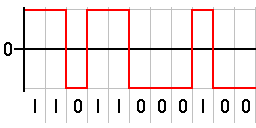
In telecommunication, a non-return-to-zero (NRZ) line code is a binary code in which ones are represented by one significant condition, usually a positive voltage, while zeros are represented by some other significant condition, usually a negative voltage, with no other neutral or rest condition.

Low-voltage differential signaling (LVDS), also known as TIA/EIA-644, is a technical standard that specifies electrical characteristics of a differential, serial signaling standard. LVDS operates at low power and can run at very high speeds using inexpensive twisted-pair copper cables. LVDS is a physical layer specification only; many data communication standards and applications use it and add a data link layer as defined in the OSI model on top of it.
A controller area network is a vehicle bus standard designed to allow microcontrollers and devices to communicate with each other. It is a message-based protocol, designed originally for multiplex electrical wiring within automobiles to save on copper, but it can also be used in many other contexts. For each device, the data in a frame is transmitted serially but in such a way that if more than one device transmits at the same time, the highest priority device can continue while the others back off. Frames are received by all devices, including by the transmitting device.
Serial Peripheral Interface (SPI) is a de facto standard for synchronous serial communication, used primarily in embedded systems for short-distance wired communication between integrated circuits.
Modified frequency modulation (MFM) is a run-length limited (RLL) line code used to encode data on most floppy disks and some hard disk drives. It was first introduced on hard disks in 1970 with the IBM 3330 and then in floppy disk drives beginning with the IBM 53FD in 1976.
Run-length limited or RLL coding is a line coding technique that is used to send arbitrary data over a communications channel with bandwidth limits. RLL codes are defined by four main parameters: m, n, d, k. The first two, m/n, refer to the rate of the code, while the remaining two specify the minimal d and maximal k number of zeroes between consecutive ones. This is used in both telecommunication and storage systems that move a medium past a fixed recording head.
In telecommunications, 8b/10b is a line code that maps 8-bit words to 10-bit symbols to achieve DC balance and bounded disparity, and at the same time provide enough state changes to allow reasonable clock recovery. This means that the difference between the counts of ones and zeros in a string of at least 20 bits is no more than two, and that there are not more than five ones or zeros in a row. This helps to reduce the demand for the lower bandwidth limit of the channel necessary to transfer the signal.
Synchronous and asynchronous transmissions are two different methods of transmission synchronization. Synchronous transmissions are synchronized by an external clock, while asynchronous transmissions are synchronized by special signals along the transmission medium.
The media-independent interface (MII) was originally defined as a standard interface to connect a Fast Ethernet media access control (MAC) block to a PHY chip. The MII is standardized by IEEE 802.3u and connects different types of PHYs to MACs. Being media independent means that different types of PHY devices for connecting to different media can be used without redesigning or replacing the MAC hardware. Thus any MAC may be used with any PHY, independent of the network signal transmission media.
Asynchronous circuit is a sequential digital logic circuit that does not use a global clock circuit or signal generator to synchronize its components. Instead, the components are driven by a handshaking circuit which indicates a completion of a set of instructions. Handshaking works by simple data transfer protocols. Many synchronous circuits were developed in early 1950s as part of bigger asynchronous systems. Asynchronous circuits and theory surrounding is a part of several steps in integrated circuit design, a field of digital electronics engineering.
SpaceWire is a spacecraft communication network based in part on the IEEE 1355 standard of communications. It is coordinated by the European Space Agency (ESA) in collaboration with international space agencies including NASA, JAXA, and RKA.
In a digitally modulated signal or a line code, symbol rate, modulation rate or baud rate is the number of symbol changes, waveform changes, or signaling events across the transmission medium per unit of time. The symbol rate is measured in baud (Bd) or symbols per second. In the case of a line code, the symbol rate is the pulse rate in pulses per second. Each symbol can represent or convey one or several bits of data. The symbol rate is related to the gross bit rate, expressed in bits per second.

IEEE Standard 1355-1995, IEC 14575, or ISO 14575 is a data communications standard for Heterogeneous Interconnect (HIC).
The primary focus of this article is asynchronous control in digital electronic systems. In a synchronous system, operations are coordinated by one, or more, centralized clock signals. An asynchronous system, in contrast, has no global clock. Asynchronous systems do not depend on strict arrival times of signals or messages for reliable operation. Coordination is achieved using event-driven architecture triggered by network packet arrival, changes (transitions) of signals, handshake protocols, and other methods.
In digital circuits, a logic level is one of a finite number of states that a digital signal can inhabit. Logic levels are usually represented by the voltage difference between the signal and ground, although other standards exist. The range of voltage levels that represent each state depends on the logic family being used. A logic-level shifter can be used to allow compatibility between different circuits.
In data networking and transmission, 64b/66b is a line code that transforms 64-bit data to 66-bit line code to provide enough state changes to allow reasonable clock recovery and alignment of the data stream at the receiver. It was defined by the IEEE 802.3 working group as part of the IEEE 802.3ae-2002 amendment which introduced 10 Gbit/s Ethernet. At the time 64b/66b was deployed, it allowed 10 Gb Ethernet to be transmitted with the same lasers used by SONET OC-192, rather than requiring the 12.5 Gbit/s lasers that were not expected to be available for several years.

In electronics, flip-flops and latches are circuits that have two stable states that can store state information – a bistable multivibrator. The circuit can be made to change state by signals applied to one or more control inputs and will output its state. It is the basic storage element in sequential logic. Flip-flops and latches are fundamental building blocks of digital electronics systems used in computers, communications, and many other types of systems.
