Computer vision is an interdisciplinary scientific field that deals with how computers can gain high-level understanding from digital images or videos. From the perspective of engineering, it seeks to understand and automate tasks that the human visual system can do.

Lidar is a method for determining ranges by targeting an object with a laser and measuring the time for the reflected light to return to the receiver. Lidar can also be used to make digital 3-D representations of areas on the earth's surface and ocean bottom, due to differences in laser return times, and by varying laser wavelengths. It has terrestrial, airborne, and mobile applications.

Machine vision (MV) is the technology and methods used to provide imaging-based automatic inspection and analysis for such applications as automatic inspection, process control, and robot guidance, usually in industry. Machine vision refers to many technologies, software and hardware products, integrated systems, actions, methods and expertise. Machine vision as a systems engineering discipline can be considered distinct from computer vision, a form of computer science. It attempts to integrate existing technologies in new ways and apply them to solve real world problems. The term is the prevalent one for these functions in industrial automation environments but is also used for these functions in other environments such as security and vehicle guidance.

Stereoscopy is a technique for creating or enhancing the illusion of depth in an image by means of stereopsis for binocular vision. The word stereoscopy derives from Greek στερεός (stereos) 'firm, solid', and σκοπέω (skopeō) 'to look, to see'. Any stereoscopic image is called a stereogram. Originally, stereogram referred to a pair of stereo images which could be viewed using a stereoscope.

A barcode reader is an optical scanner that can read printed barcodes, decode the data contained in the barcode and send the data to a computer. Like a flatbed scanner, it consists of a light source, a lens and a light sensor translating for optical impulses into electrical signals. Additionally, nearly all barcode readers contain decoder circuitry that can analyze the barcode's image data provided by the sensor and sending the barcode's content to the scanner's output port.

An image scanner—often abbreviated to just scanner, is a device that optically scans images, printed text, handwriting or an object and converts it to a digital image. Commonly used in offices are variations of the desktop flatbed scanner where the document is placed on a glass window for scanning. Hand-held scanners, where the device is moved by hand, have evolved from text scanning "wands" to 3D scanners used for industrial design, reverse engineering, test and measurement, orthotics, gaming and other applications. Mechanically driven scanners that move the document are typically used for large-format documents, where a flatbed design would be impractical.

Traditional animation is an animation technique in which each frame is drawn by hand. The technique was the dominant form of animation in cinema until the advent of computer animation.

An autostereogram is a single-image stereogram (SIS), designed to create the visual illusion of a three-dimensional (3D) scene from a two-dimensional image. In order to perceive 3D shapes in these autostereograms, one must overcome the normally automatic coordination between accommodation (focus) and horizontal vergence. The illusion is one of depth perception and involves stereopsis: depth perception arising from the different perspective each eye has of a three-dimensional scene, called binocular parallax.
2.5D perspective refers to one of two things:

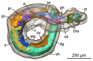
Confocal microscopy, most frequently confocal laser scanning microscopy (CLSM) or laser confocal scanning microscopy (LCSM), is an optical imaging technique for increasing optical resolution and contrast of a micrograph by means of using a spatial pinhole to block out-of-focus light in image formation. Capturing multiple two-dimensional images at different depths in a sample enables the reconstruction of three-dimensional structures within an object. This technique is used extensively in the scientific and industrial communities and typical applications are in life sciences, semiconductor inspection and materials science.
In visual effects, match moving is a technique that allows the insertion of computer graphics into live-action footage with correct position, scale, orientation, and motion relative to the photographed objects in the shot. The term is used loosely to describe several different methods of extracting camera motion information from a motion picture. Sometimes referred to as motion tracking or camera solving, match moving is related to rotoscoping and photogrammetry. Match moving is sometimes confused with motion capture, which records the motion of objects, often human actors, rather than the camera. Typically, motion capture requires special cameras and sensors and a controlled environment. Match moving is also distinct from motion control photography, which uses mechanical hardware to execute multiple identical camera moves. Match moving, by contrast, is typically a software-based technology, applied after the fact to normal footage recorded in uncontrolled environments with an ordinary camera.
Three-dimensional face recognition is a modality of facial recognition methods in which the three-dimensional geometry of the human face is used. It has been shown that 3D face recognition methods can achieve significantly higher accuracy than their 2D counterparts, rivaling fingerprint recognition.

A coordinate measuring machine (CMM) is a device that measures the geometry of physical objects by sensing discrete points on the surface of the object with a probe. Various types of probes are used in CMMs, including mechanical, optical, laser, and white light. Depending on the machine, the probe position may be manually controlled by an operator or it may be computer controlled. CMMs typically specify a probe's position in terms of its displacement from a reference position in a three-dimensional Cartesian coordinate system. In addition to moving the probe along the X, Y, and Z axes, many machines also allow the probe angle to be controlled to allow measurement of surfaces that would otherwise be unreachable.

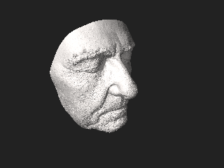
3D scanning is the process of analyzing a real-world object or environment to collect data on its shape and possibly its appearance. The collected data can then be used to construct digital 3D models.
HoloVID is a tool originally developed for the holographic dimensional measurement of the internal isogrid structural webbing of the Delta family of launch vehicles in 1981 by Mark Slater.
In computer vision and computer graphics, 3D reconstruction is the process of capturing the shape and appearance of real objects. This process can be accomplished either by active or passive methods. If the model is allowed to change its shape in time, this is referred to as non-rigid or spatio-temporal reconstruction.
A structured-light 3D scanner is a 3D scanning device for measuring the three-dimensional shape of an object using projected light patterns and a camera system.

A time-of-flight camera is a range imaging camera system employing time-of-flight techniques to resolve distance between the camera and the subject for each point of the image, by measuring the round trip time of an artificial light signal provided by a laser or an LED. Laser-based time-of-flight cameras are part of a broader class of scannerless LIDAR, in which the entire scene is captured with each laser pulse, as opposed to point-by-point with a laser beam such as in scanning LIDAR systems. Time-of-flight camera products for civil applications began to emerge around 2000, as the semiconductor processes allowed the production of components fast enough for such devices. The systems cover ranges of a few centimeters up to several kilometers. The distance resolution is about 1 cm. The spatial resolution of time-of-flight cameras is generally low compared to standard 2D video cameras, with most commercially available devices at 320 × 240 pixels or less as of 2011. Compared to other 3D laser scanning methods for capturing 3D images, TOF cameras operate more quickly by providing up to 160 operations per second.
HP TopShot technology is digital camera technology that serves as the scanning mechanism on a LaserJet Multifunctional Printer (MFP). TopShot operates like a small photography studio that captures three-dimensional objects on a specially-designed platform on top of the MFP. It also functions as a document scanner to capture text and images that are on paper. TopShot can capture any object that fits on its scanning platform.

3D reconstruction from multiple images is the creation of three-dimensional models from a set of images. It is the reverse process of obtaining 2D images from 3D scenes.
