A die in polymer processing is a metal restrictor or channel capable of providing a constant cross sectional profile to a stream of liquid polymer. This allows for continuous processing of shapes such as sheets, films, pipes, rods, and other more complex profiles. This is a continuous process, allowing for constant production (assuming constant supply of polymer melt), as opposed to a sequential (non-constant) process such as injection molding.
Die forming typically occurs immediately after polymer melt has exited an extruder. The most basic process involves guiding the stream of molten polymer under pressure through a die, which three distinct regions: manifold, approach, and lip. The 'manifold' serves to channel the polymer melt from its initial extrusion point to a near-net-shape of the final product. The 'approach' region further guides the melt into the final shape, and begins to correct for any non-uniform flow. Finally, the 'lip' forms the melt into the final desired cross section and compensates for any remaining flow asymmetry. After exiting the lip of the die, the polymer melt will undergo die swell before curing. Die swell is an expansion of the melt as the pressure is released, and is dependent on polymer chemistry and die design. After curing, the solid, continuous part is drawn onto a take-up roller or cut into transportable lengths, depending on the type of part. This process may vary significantly depending on the type of die and extrusion process.[1]
Sheet/film extrusion
There are two major types of dies used in flat sheet extrusion: T-shaped and coat-hanger. A T-shaped die consists of two arms extending at right angles from the initial extrusion channel; these arms have a small slit along their length to allow the polymer melt to flow through. The melt is then further thinned by a short, flat approach before being pushed through the lips of the die. This setup can cause non-uniform flow across the width of the extruded sheet, with the melt at the center flowing faster than the melt at the edges of the die, resulting in buckling and other defects after exiting the die.[2]
A more modern design is the coat-hanger die. This die differs from the T-shaped die in that the arms are not at right angles to the input direction; instead, the arms are at a shallower angle and are often curved. The arms also have a variable diameter, tapering down to a smaller radius further from the input channel. The approach portion of coat-hanger dies are longer than their T-shaped counterparts, further reducing any flow nonuniformity. Finally, the melt is extruded through lips as in the T-shaped die.
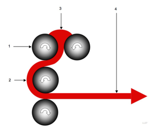
For products such as plastic sheets or films, cooling is achieved by pulling through a set of cooling rolls (also known as calender or chill rolls), usually 3 or 4 in number. In sheet extrusion, these rolls not only deliver the necessary cooling but also help determine sheet thickness and surface texture (in case of structured rolls; i.e. smooth, levant, haircell, etc.). A common processing defect known as nerve may occur when contact time between the rollers and extrudate is too brief, resulting in insufficient cooling time.
Coextrusion is common in sheet and film extrusion, allowing for speedy production of multi-layered parts. This is accomplished by joining multiple polymer melts in either the manifold or approach stage. Layers of different thicknesses may be formed by introducing melts at different flow rates or different manifold sizes.
Blown film extrusion
Blow extrusion of plastic film
The manufacture of plastic film for products such as shopping bags and continuous sheeting is achieved using a blown film line.[3] Polymer melt from an extruder is fed through an upright die with an annular opening. There are several types of dies that can be used, depending on final requirements of film quality and characteristics of the polymer melt: spider, crosshead, and spiral dies.
A spider die consists of an internal mandrel connected to the outer die wall by several "legs", and is a moderately complex design. The resulting film will feature weld lines wherever legs were present. These weld lines are weaker than the surrounding polymer, and may also have different optical characteristics, such as haze. This weakness is caused by incomplete healing of the polymer molecular matrix. Furthermore, a pressure gradient produced by the spider legs will cause nonuniform die swell, resulting in nonuniform film thickness.
A crosshead die splits the melt flow in two at the manifold inlet, recombining them at the opposite side of a cylindrical center mandrel. This relatively simple design results in non-symmetrical flow, as molecules take longer to reach the opposite side than the close side of the mandrel. As such, the resulting film will not be of uniform thickness. To reduce this nonuniformity, inlet diameters can be varied, and various inserts can be added to minimize stagnant regions.
A spiral die is the most complex of the three major blown film die types. The polymer melt is evenly distributed into several feed tubes, which wind around a central mandrel. Each of these feed tubes is connected to the space between the mandrel and outer die walls; the feed tubes gradually diminish in diameter as they spiral around the mandrel. At the same time, the space between the mandrel and outer die walls is increased. This allows the polymer melt to layer and blend, resulting in a uniform melt profile free of weld lines. This die design produces the most uniform films, but is also the most expensive.
Air pressure is introduced through the extrusion die so that after the polymer melt leaves the lip of the die, it expands in circumference. The tubing is also drawn along its length faster than it is being extruded. This leads to thinning of the film as it is expanded in both the draw (or machine) direction, and in the transverse (or hoop) direction. The ratio of the blown diameter to the extruded diameter is known as the blow-up ratio, and affects the resulting physical properties of the film, such as stiffness and strength. Film thickness and blow-up ratio can be varied by altering the take-up rate of the rollers, the internal pressure in the blown tube, and the melt extrusion rate.
As the film is drawn upwards, it is cooled by a ring of air blowers so that the melt first becomes an amorphous viscoelastic solid, and then a semicrystalline solid, at what is known as the frost line. After solidification, the blown film tube continues to be cooled as it is pulled up by several sets of rollers, deflating the film to form lay-flat tubing. The flat film is then wound on a spool before further processing or shipping. The height of the film line is often 10 times the diameter of the blown tube or more; film lines in excess of 30 meters are possible.
Once the film tube is completely cooled, it is taken up by several nip rollers. The width of the resulting doubled-over flat film is equal to half of the blown tube's circumference. The film is then either spooled as a flattened tube, or immediately split into two separate pieces. At this point, the film is ready for further processing, such as printing or cutting into final shape.
Overjacketing extrusion is a coating process, in which individual bare wires or bundles of pre-coated wires are coated with a layer of insulating polymer. A wide variety of materials may be used, depending on the specific application. For many applications, such as insulated cables, the polymer should be a good insulator, flexible, and wear resistant.[4]
In this process, a wire (or bundle of wires) is preheated to above the glass transition or melting temperature of the polymer coating that is to be applied. This is to ensure adhesion of the new coating. Next, this preheated bare wire is pulled through a die which places a thin coating of polymer around the wire. Due to the geometry of the dies used, relatively high extrusion rates are possible while still avoiding melt fracture. The newly coated wire is then drawn through an air or gas flame to smooth the surface of the coating, and finally a water bath to fully cool the coated wire. Coated wires are now spooled to prepare for further processing, if desired.
There are two major types of dies used in overjacketing extrusion, both based on an overall crosshead design. Regardless of die type used, the polymer melt is often extruded at a rate less than the speed of the bare wire that is drawn through the die, typically on the order of 1-4 times the speed of the melt. This causes the polymer jacket to extend, thin, and tighten around the central wire, increasing adhesion of the new layer.
The first dye type is an annular, or tubing/jacketing, die that extrudes a tube of polymer that is initially not touching the bare wire. A vacuum is then applied to the still-molten polymer tube, causing it to be drawn onto and bond to the surface of the bare wire. This type of die is typically used to coat very thin wires with polymer jacketing that is highly viscous.
The second die type, known as a pressure type die, relies on contact between the jacketing polymer and bare wire inside the die. In this die type, a ring of polymer melt under pressure is forced around the bare wire. Due to the applied pressure of the melt, the opening around the inlet for the bare wire must be very small, on the order of 0.05mm. The size of the exit opening controls the thickness of the resulting coating. This type of die results in more intimate contact between the outer coating and the bare wire than the jacketing die.
Fiber drawing (polymers)
Fiber drawing is a hybrid process, in which gravity or another force is used to geometrically and mechanically alter the extruded fibers. This process not only reduces the cross section of the polymer fiber, but also increases the strength of the fibers by aligning the individual polymer molecules.
Before drawing, polymer melt is pushed through a die with a large number of small holes, known as a spinneret. Typically, the fibers are air cooled without any need for curing. If curing is needed, two methods are available: dry and wet spinning. In wet spinning, the polymer is dissolved and extruded through a spinneret into a chemical bath. In dry spinning, a solvent is allowed to evaporate as the fibers are cooled.
Typically, fiber drawing occurs immediately after spinning. Application of an external force, either from gravity or take up rollers, causes the fibers to contract laterally and lengthen. This orients the individual polymer molecules along the length of the fiber, increasing strength. The radius of the fibers have been shown to decrease hyperbolically as they lengthen. Once the fibers solidify, they may begin to crystallize, with each grain initially randomly oriented. Further drawing will cause the crystal grains to elongate and reorient in the direction of the tensile axis, further strengthening the fibers.
Spinning stability
In practice, not all polymers are suitable for fiber spinning or drawing. This is particularly an issue in extensional-thinning polymers, where capillary failure or necking can cause separation of the melt before solidification.
Draw resonance is the most common issue that can occur during drawing of the polymer melt, regardless of polymer suitability. Resonance occurs when the rate of mass flow is not constant between the spinneret and fiber take up roller, despite being constant at each of those individual components. When the mass flow rate is not constant, the diameter of the fiber will vary to accommodate the variation. Once started, this resonance may not correct itself, requiring a complete shutdown of the extrusion line.
It has been shown that draw resonance occurs once a critical drawdown ratio is exceeded; this ratio is dependent on the flow behavior (i.e. Newtonian, shear thinning) and viscoelastic behavior of the fluid. Draw resonance has not been found to be a function of the flow rate, however. A polymer melt approaching a Newtonian fluid such as PET can have a drawdown ratio of around 20, whereas highly shear thinning and viscoelastic polymer melts such as polyethylene, polystyrene, and polypropylene may have critical drawdown ratios as low as 3.
Tube forming
Tube forming dies allow for continuous extrusion of thick walled (relative to blown film extrusion) tubes and pipes.[5] The dies themselves are almost identical to those used in blown film extrusion; the only major difference is the gap between the inner mandrel and outer die wall. Once the polymer melt is extruded from the die, it is pulled away by take-up rollers. Cooling is accomplished through the use of water baths, or a large number of cooling fans. After cooling, the tube is either wound onto large spools (if flexible), or cut into pre-set lengths and stacked (if stiff).
Tubing with multiple lumens (holes) must be made for specialty applications. For these applications, the tooling is made by placing more than one mandrel in the center of the die, to produce the number of lumens necessary. In most cases, these mandrels are supplied with air pressure from different sources. In this way, the individual lumen sizes can be adjusted by adjusting the pressure to the individual mandrels.
Profile extrusion
Profile extrusion, the extrusion of complex shapes such as rain gutters, structural supports, and other components, brings with it some of the most complex die designs of any extrusion process.[6] This difficulty is due to two primary concerns: producing the initial, still molten profile, and then controlling for asymmetrical shrinkage and die swell due to varying wall thicknesses.
Unlike in blown film, pipe, and sheet extrusion, the dies used in profile extrusion are rarely round or completely flat. Whereas a round (or flat) profile has uniform flow rates along all edges, this is not the case for more complex shapes. Take, for instance, the example of a simple, solid, square profile. The velocity of the melt is highest at the center of the die, and slowest at the edges and corners due to friction between the melt and die walls. When moving from the center of the die to the midpoint of one of the edges, the velocity gradient is high, especially near the outer die wall. However, when moving from the center to one of the corners, the velocity gradient is more gradual. As a result, the extruded square profile will experience more die swell at the edges than the corners, causing the once square profile to become more circular. This can be compensated for by bowing in the sides of the die so it approximates the shape of a four-pointed star; the sides of the polymer melt will now swell to the intended dimensions.
As the desired profile becomes more complex, the die in turn becomes more complex. Care must be taken to minimize weld lines, as well as ensuring complete filling of the die to prevent bubbles and other defects in the finished extruded profile. After the initial extrusion is complete, the molten polymer profile is cooled slightly before being run through a sizing die. This die ensures that the extruded profile meets specifications, and can correct the shape to fit those specifications. After sizing is complete, the profile is cooled before any further processing.
Coextrusion
5 :5 Layer Co-Extrusion of Cosmetic "Squeeze" Tube
In practice, many films, sheets, and other extruded parts are multilayered; this allows for optimization of a wide range of properties, such as oxygen permeability, strength, and stiffness. The primary difficulty of coextrusion is bridging the gap in properties between each layer.[7] Adding a thin "compatibility" layer is a common solution to alleviating viscosity or stiffness incompatibilities.[8]
There are two major die types for coextrusion: single manifold and multi manifold. Both types rely on a separate extruder for each polymer chemistry. In multi manifold dies, each layer is extruded separately and only combined just before the die lips. This die type is expensive due to the complex tooling required, but can alleviate vast differences in rheological behavior between the various layers. Single manifold dies form the multiple layers into a single layer, allowing contact between the polymer layers for a longer period of time. This ensures optimal bonding, but comes at the consequence of needing higher compatibility polymers.
There are two types of processing defects that can occur during coextrusion. The first defect is interface instability, causing unintended interface shapes. This can cause "encapsulation" of the higher viscosity melt by the lower viscosity melt, leading to poor final performance of the extruded part. The severity of this type of defect is proportional to the difference in viscosities between the two polymer melts. The other type of defect forms from oscillations in the melt flow, causing small wavelike patterns on the surface of the melt and reducing optical transparency.
Related Research Articles
Extrusion is a process used to create objects of a fixed cross-sectional profile by pushing material through a die of the desired cross-section. Its two main advantages over other manufacturing processes are its ability to create very complex cross-sections; and to work materials that are brittle, because the material encounters only compressive and shear stresses. It also creates excellent surface finish and gives considerable freedom of form in the design process.
A calender is a series of hard pressure rollers used to finish or smooth a sheet of material such as paper, textiles, or plastics. Calender rolls are also used to form some types of plastic films and to apply coatings. Some calender rolls are heated or cooled as needed. Calenders are sometimes misspelled calendars.
Drawing is a metalworking process that uses tensile forces to stretch (elongate) metal, glass, or plastic. As the metal is drawn (pulled), it stretches to become thinner, to achieve a desired shape and thickness. Drawing is classified into two types: sheet metal drawing and wire, bar, and tube drawing. Sheet metal drawing is defined as a plastic deformation over a curved axis. For wire, bar, and tube drawing, the starting stock is drawn through a die to reduce its diameter and increase its length. Drawing is usually performed at room temperature, thus classified as a cold working process; however, drawing may also be performed at elevated temperatures to hot work large wires, rods or hollow sections in order to reduce forces.
A coating is a covering that is applied to the surface of an object, usually referred to as the substrate. The purpose of applying the coating may be decorative, functional, or both.
Blow molding is a manufacturing process for forming and joining together hollow plastic parts. It is also used for forming glass bottles or other hollow shapes.
Ceramic forming techniques are ways of forming ceramics, which are used to make everything from tableware such as teapots to engineering ceramics such as computer parts. Pottery techniques include the potter's wheel, slip casting and many others.
Powder coating is a type of coating that is applied as a free-flowing, dry powder. Unlike conventional liquid paint which is delivered via an evaporating solvent, powder coating is typically applied electrostatically and then cured under heat or with ultraviolet light. The powder may be a thermoplastic or a thermoset polymer. It is usually used to create a hard finish that is tougher than conventional paint. Powder coating is mainly used for coating of metals, such as household appliances, aluminium extrusions, drum hardware, automobiles, and bicycle frames. Advancements in powder coating technology like UV curable powder coatings allow for other materials such as plastics, composites, carbon fiber, and MDF to be powder coated due to the minimum heat and oven dwell time required to process these components.
Pneumatic tires are manufactured according to relatively standardized processes and machinery, in around 455 tire factories in the world. With over 1 billion tires manufactured worldwide annually, the tire industry is a major consumer of natural rubber. Tire factories start with bulk raw materials such as synthetic rubber, carbon black, and chemicals and produce numerous specialized components that are assembled and cured.
Nonwoven fabric is a fabric-like material made from staple fibre (short) and long fibres, bonded together by chemical, mechanical, heat or solvent treatment. The term is used in the textile manufacturing industry to denote fabrics, such as felt, which are neither woven nor knitted. Some non-woven materials lack sufficient strength unless densified or reinforced by a backing. In recent years, non-wovens have become an alternative to polyurethane foam.
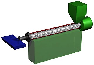
Plastics extrusion is a high-volume manufacturing process in which raw plastic is melted and formed into a continuous profile. Extrusion produces items such as pipe/tubing, weatherstripping, fencing, deck railings, window frames, plastic films and sheeting, thermoplastic coatings, and wire insulation.
Extrusion coating is the coating of a molten web of synthetic resin onto a substrate material. It is a versatile coating technique used for the economic application of various plastics, notably polyethylene, onto paperboard, corrugated fiberboard, paper, aluminium foils, cellulose, Non-wovens, or plastic films.
Curtain coating is a process that creates an uninterrupted curtain of fluid that falls onto a substrate. The substrate is transported on a conveyor belt or calender rolls at a regulated speed through the curtain to ensure an even coat of the die. The curtain is created by using a slit or die at the base of the holding tank, allowing the liquid to fall upon the substrate. Some polymers are melted and extruded for coating. Many manufactures will also include a catch pan to retrieve and reuse the excess fluid.
Plastic film is a thin continuous polymeric material. Thicker plastic material is often called a "sheet". These thin plastic membranes are used to separate areas or volumes, to hold items, to act as barriers, or as printable surfaces.
Cladding is the bonding together of dissimilar metals. It is different from fusion welding or gluing as a method to fasten the metals together. Cladding is often achieved by extruding two metals through a die as well as pressing or rolling sheets together under high pressure.
A film blowing machine involves one process used to make plastic film. Extruded tubular processing is most often used with polyethylene films but can be used with other polymers. The film may be laminating film, shrink film, agricultural covering film, bags or film for textiles and clothing, and other packaging materials.
Guardian is the trademark name of a polymer originally manufactured by Securency International, a joint venture between the Reserve Bank of Australia and Innovia Films Ltd. The latter completed acquisition of the former's stake in 2013.
Thermoplastics containing short fiber reinforcements were first introduced commercially in the 1960s. The most common type of fibers used in short fiber thermoplastics are glass fiber and carbon fiber . Adding short fibers to thermoplastic resins improves the composite performance for lightweight applications. In addition, short fiber thermoplastic composites are easier and cheaper to produce than continuous fiber reinforced composites. This compromise between cost and performance allows short fiber reinforced thermoplastics to be used in myriad applications.
Extrusion welding is one of the processes used to weld thermoplastics and composites, developed in the 1960s as an evolution of hot gas welding. It can be a manual or automated process.
Covema srl was a historic Italian company specializing in the design of plastic processing machinery, based in Milan, via Fontana 1. Founded in 1953 by the Terragni brothers, it also included the companies Corima spa, GBF spa, GBF iberica, RIAP srl, FIRS spa, Covepla Spain, Italproducts srl, Omam spa, TPA srl, AGRIPAK srl, Floraplant srl, Interfinance SA, Technical Die spa, Covema SAE. The technology that Covema has developed since the 1950s is merged into Agripak srl based in Milano and managed by the sons of Marco Terragni: Fabio Terragni (president), Patrizia Terragni and Massimo Terragni.
Slot-die coating is a coating technique for the application of solution, slurry, or extruded thin films onto typically flat substrates such as glass, metal, paper, fabric or plastic foils. The process was first developed for the industrial production of photographic papers in the 1950's. It has since become relevant in numerous commercial processes and nanomaterials related research fields.
References
↑ Tadmor and Gogos (2006). Principles of Polymer Processing. John Wiley and Sons. ISBN978-0-471-38770-1
This page is based on this Wikipedia article Text is available under the CC BY-SA 4.0 license; additional terms may apply. Images, videos and audio are available under their respective licenses.