The Pelton wheel or Pelton Turbine is an impulse-type water turbine invented by American inventor Lester Allan Pelton in the 1870s. The Pelton wheel extracts energy from the impulse of moving water, as opposed to water's dead weight like the traditional overshot water wheel. Many earlier variations of impulse turbines existed, but they were less efficient than Pelton's design. Water leaving those wheels typically still had high speed, carrying away much of the dynamic energy brought to the wheels. Pelton's paddle geometry was designed so that when the rim ran at half the speed of the water jet, the water left the wheel with very little speed; thus his design extracted almost all of the water's impulse energy—which made for a very efficient turbine.
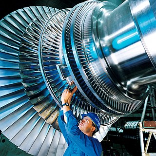
A steam turbine is a machine that extracts thermal energy from pressurized steam and uses it to do mechanical work on a rotating output shaft. Its modern manifestation was invented by Charles Parsons in 1884. Fabrication of a modern steam turbine involves advanced metalwork to form high-grade steel alloys into precision parts using technologies that first became available in the 20th century; continued advances in durability and efficiency of steam turbines remains central to the energy economics of the 21st century.
Bernoulli's principle is a key concept in fluid dynamics that relates pressure, speed and height. Bernoulli's principle states that an increase in the speed of a fluid occurs simultaneously with a decrease in static pressure or the fluid's potential energy. The principle is named after the Swiss mathematician and physicist Daniel Bernoulli, who published it in his book Hydrodynamica in 1738. Although Bernoulli deduced that pressure decreases when the flow speed increases, it was Leonhard Euler in 1752 who derived Bernoulli's equation in its usual form.

Centrifugal compressors, sometimes called impeller compressors or radial compressors, are a sub-class of dynamic axisymmetric work-absorbing turbomachinery.
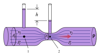
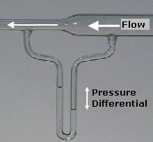
The Venturi effect is the reduction in fluid pressure that results when a fluid flows through a constricted section of a pipe. The Venturi effect is named after its discoverer, the 18th-century Italian physicist Giovanni Battista Venturi.

The Francis turbine is a type of water turbine. It is an inward-flow reaction turbine that combines radial and axial flow concepts. Francis turbines are the most common water turbine in use today, and can achieve over 95% efficiency.

An axial compressor is a gas compressor that can continuously pressurize gases. It is a rotating, airfoil-based compressor in which the gas or working fluid principally flows parallel to the axis of rotation, or axially. This differs from other rotating compressors such as centrifugal compressor, axi-centrifugal compressors and mixed-flow compressors where the fluid flow will include a "radial component" through the compressor.

Hydraulic head or piezometric head is a specific measurement of liquid pressure above a vertical datum.

Centrifugal pumps are used to transport fluids by the conversion of rotational kinetic energy to the hydrodynamic energy of the fluid flow. The rotational energy typically comes from an engine or electric motor. They are a sub-class of dynamic axisymmetric work-absorbing turbomachinery. The fluid enters the pump impeller along or near to the rotating axis and is accelerated by the impeller, flowing radially outward into a diffuser or volute chamber (casing), from which it exits.
In a hydraulic circuit, net positive suction head (NPSH) may refer to one of two quantities in the analysis of cavitation:
- The Available NPSH (NPSHA): a measure of how close the fluid at a given point is to flashing, and so to cavitation. Technically it is the absolute pressure head minus the vapour pressure of the liquid.
- The Required NPSH (NPSHR): the head value at the suction side required to keep the fluid away from cavitating.
The Euler number (Eu) is a dimensionless number used in fluid flow calculations. It expresses the relationship between a local pressure drop caused by a restriction and the kinetic energy per volume of the flow, and is used to characterize energy losses in the flow, where a perfect frictionless flow corresponds to an Euler number of 0. The inverse of the Euler number is referred to as the Ruark Number with the symbol Ru.
There are three dimensionless numbers that may be referred to as the cavitation number in various scenarios: the cavitation number for hydrodynamic cavitation, the Thoma number for cavitation in pumps, and the Garcia-Atance number for ultrasonic cavitation.

In aerodynamics, Betz's law indicates the maximum power that can be extracted from the wind, independent of the design of a wind turbine in open flow. It was published in 1919 by the German physicist Albert Betz. The law is derived from the principles of conservation of mass and momentum of the air stream flowing through an idealized "actuator disk" that extracts energy from the wind stream. According to Betz's law, no aerodynamically thin windmill of any mechanism can capture more than 16/27 (59.3%) of the kinetic energy in wind. The factor 16/27 (0.593) is known as Betz's coefficient. Practical utility-scale wind turbines achieve at peak 75–80% of the Betz limit.
In fluid dynamics the Borda–Carnot equation is an empirical description of the mechanical energy losses of the fluid due to a (sudden) flow expansion. It describes how the total head reduces due to the losses. This is in contrast with Bernoulli's principle for dissipationless flow, where the total head is a constant along a streamline. The equation is named after Jean-Charles de Borda (1733–1799) and Lazare Carnot (1753–1823).
In turbomachinery, degree of reaction or reaction ratio (R) is defined as the ratio of the static pressure rise in the rotating blades of a compressor (or drop in turbine blades) to the static pressure rise in the compressor stage (or drop in a turbine stage). Alternatively it is the ratio of static enthalpy change in the rotor to the static enthalpy change in the stage.
Blade element momentum theory is a theory that combines both blade element theory and momentum theory. It is used to calculate the local forces on a propeller or wind-turbine blade. Blade element theory is combined with momentum theory to alleviate some of the difficulties in calculating the induced velocities at the rotor.
An axial fan is a type of fan that causes gas to flow through it in an axial direction, parallel to the shaft about which the blades rotate. The flow is axial at entry and exit. The fan is designed to produce a pressure difference, and hence force, to cause a flow through the fan. Factors which determine the performance of the fan include the number and shape of the blades. Fans have many applications including in wind tunnels and cooling towers. Design parameters include power, flow rate, pressure rise and efficiency.
Isentropic nozzle flow describes the movement of a gas or fluid through a narrowing opening without an increase or decrease in entropy.
Cavitation modelling is a type of computational fluid dynamic (CFD) that represents the flow of fluid during cavitation. It covers a wide range of applications, such as pumps, water turbines, pump inducers, and fuel cavitation in orifices as commonly encountered in fuel injection systems.
Radial means that the fluid is flowing in radial direction that is either from inward to outward or from outward to inward. If the fluid is flowing from inward to outward then it is called outflow radial turbine.
- In such turbines, the water enters at the centre of the wheel and then flows outwards.
- Here guide mechanism is surrounded by the runner.
- In this turbine, the inner diameter of the runner is the inlet and outer diameter is an outlet.