Related Research Articles
The unified modeling language (UML) is a general-purpose visual modeling language that is intended to provide a standard way to visualize the design of a system.
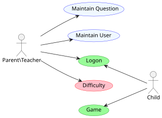
An actor in the Unified Modeling Language (UML) "specifies a role played by a user or any other system that interacts with the subject."

In software engineering, a sequence diagram shows process interactions arranged in time sequence. This diagram depicts the processes and objects involved and the sequence of messages exchanged as needed to carry out the functionality. Sequence diagrams are typically associated with use case realizations in the 4+1 architectural view model of the system under development. Sequence diagrams are sometimes called event diagrams or event scenarios.

In software engineering, a class diagram in the Unified Modeling Language (UML) is a type of static structure diagram that describes the structure of a system by showing the system's classes, their attributes, operations, and the relationships among objects.

A package diagram in the Unified Modeling Language depicts "specializations for Models and for Profiles that organize extensions to UML."
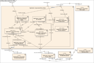
In Unified Modeling Language (UML), a component diagram depicts how components are wired together to form larger components or software systems. They are used to illustrate the structure of arbitrarily complex systems.

Activity diagrams are graphical representations of workflows of stepwise activities and actions with support for choice, iteration, and concurrency. In the Unified Modeling Language, activity diagrams are intended to model both computational and organizational processes, as well as the data flows intersecting with the related activities. "Object nodes hold data that is input to and output from executable nodes, and moves across object flow edges. Control nodes specify sequencing of executable nodes via control flow edges." In other words, although activity diagrams primarily show the overall control flow, they can also include elements showing the data flow between activities through one or more data stores.

A communication diagram in Unified Modeling Language (UML) 2.5.1 is a simplified version of the UML 1.x collaboration diagram.
A timing diagram in Unified Modeling Language 2.5.1 is a specific type of interaction diagram, where the focus is on timing constraints.
Executable UML is both a software development method and a highly abstract software language. It was described for the first time in 2002 in the book "Executable UML: A Foundation for Model-Driven Architecture". The language "combines a subset of the UML graphical notation with executable semantics and timing rules." The Executable UML method is the successor to the Shlaer–Mellor method.
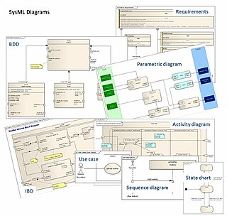
The systems modeling language (SysML) is a general-purpose modeling language for systems engineering applications. It supports the specification, analysis, design, verification and validation of a broad range of systems and systems-of-systems.

In object-oriented programming, an object diagram in the Unified Modeling Language (UML) is a diagram that shows a complete or partial view of the structure of a modeled system at a specific time.
Composite structure diagram in the Unified Modeling Language (UML) is a type of static structure diagram that shows the internal structure of a class and the collaborations that this structure makes possible.
In the Unified Modeling Language 1.x, powertype is a keyword for a specific UML stereotype, and applies to a class or dependency. Powertype shows a classifier whose instances (objects) are children of the given parent.
In the Unified Modeling Language (UML), a Dependency is "a Relationship that signifies that a single model Element or a set of model Elements requires other model Elements for their specification or implementation." "This means that the complete semantics of the client Element(s) are either semantically or structurally dependent on the definition of the supplier Element(s)." Two or more elements in this relationship are called tuples.

Interaction Overview Diagram is one of the fourteen "nominative" types of diagrams of the Unified Modeling Language (UML), which can picture a control flow with nodes that can contain interaction diagrams.

A component in the Unified Modeling Language represents a modular part of a system that encapsulates the state and behavior of a number of classifiers. Its behavior is defined in terms of provided and required interfaces, is self-contained, and substitutable. A number of UML standard stereotypes exist that apply to components.

An artifact in the Unified Modeling Language (UML) is the "specification of a physical piece of information that is used or produced by a software development process, or by deployment and operation of a system."
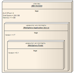
A node in the Unified Modeling Language (UML) is a computational resource upon which UML artifacts may be deployed for execution.

In Unified Modeling Language in the field of software engineering, a profile diagram operates at the metamodel level to show stereotypes as classes with the «stereotype» stereotype, and profiles as packages with the «profile» stereotype. The extension relation indicates what metamodel element a given stereotype is extending.
References
- 1 2 "Element". Unified Modeling Language 2.5.1. OMG Document Number formal/2017-12-05. Object Management Group Standards Development Organization (OMG SDO). December 2017. p. 43.
- 1 2 3 4 5 OMG Unified Modeling Language, Superstructure, Version 2.4.1
- 1 2 UML 2 Certification Guide, Tim Weilkiens and Bernd Oestereich - ISBN 0-12-373585-8