Enigma rotor details

Last updated

This article contains technical details about the rotors of the Enigma machine. Understanding the way the machine encrypts requires taking into account the current position of each rotor, the ring setting and its internal wiring.

Contents

Physical design of rotors

Detail of rotor internal structure and wiring on display at the US National Cryptologic Museum Enigma rotor wiring.png
Detail of rotor internal structure and wiring on display at the US National Cryptologic Museum
Exploded view of an Enigma rotor Three rotors in sequence
Enigma rotor exploded view.png
  1. notched ring
  2. marking dot for "A" contact
  3. alphabet tyre
  4. plate contacts
  5. wire connections
  6. pin contacts
  7. spring-loaded ring adjusting lever
  8. hub
  9. finger wheel
  10. ratchet wheel
Enigma rotor set.png

Rotor electrical view

The scrambling action of the Enigma rotors shown for two consecutive letters -- current is passed through the rotors, around the reflector, and back out through the rotors again. Note: The grayed-out lines represent other possible circuits within each rotor, which are hard-wired to contacts on each rotor. Enigma-action.svg
The scrambling action of the Enigma rotors shown for two consecutive letters current is passed through the rotors, around the reflector, and back out through the rotors again. Note: The grayed-out lines represent other possible circuits within each rotor, which are hard-wired to contacts on each rotor.

No letter can map to itself, a cryptographic weakness caused by the same wires being used for forwards and backwards legs.

Rotor offset

The effect of rotation on the rotors can be demonstrated with some examples.

As an example, let us take rotor type I of Enigma I (see table below) without any ring setting offset. It can be seen that an A is encoded as an E, a B encoded as a K, and a K is encoded as an N. Notice that every letter is encoded into another.

In the case of the reflectors, in this example Wide B is taken (Reflector B in the table below) where an A is returned as a Y and the Y is returned as an A. Notice that the wirings are connected as a loop between two letters.

When a rotor has stepped, the offset must be taken into account to know what the output is, and where it enters the next rotor.

If for example rotor I is in the B-position, an A enters at the letter B which is wired to the K. Because of the offset this K enters the next rotor in the J position.

With the rotors I, II and III (from left to right), wide B-reflector, all ring settings in A-position, and start position AAA, typing AAAAA will produce the encoded sequence BDZGO[ citation needed ].

Ring setting

The ring settings, or Ringstellung, are used to change the position of the alphabet ring relative to the internal wiring. Notch and alphabet ring are fixed together. Changing the ring setting will therefore change the positions of the wiring, relative to the turnover-point and start position.

The ring setting will rotate the wiring. Where rotor I in the A-position normally encodes an A into an E, with a ring setting offset B-02 it will be encoded into K

As mentioned before these encodings only happen after the key is pressed and the rotor has turned. Tracing the signal on the rotors AAA is therefore only possible if a key is pressed while the rotors were in the position AAZ and the ring settings are all on 01 or A.

With the rotors I, II, III (from left to right), wide B-reflector, all ring settings in B-position, and start position AAA, typing AAAAA will produce the encoded sequence EWTYX.

Rotor wiring tables

This table shows how the internal wiring connects the right side of the rotor (with the spring-loaded contacts) to the left side. Each rotor is a simple substitution cipher. The letters are listed as connected to alphabet order. If the first letter of a rotor is E, this means that the A is wired to the E. This does not mean that E is wired to A; such looped wiring is only the case with the reflectors.

Terminology
Rotor Wiring [1]
Rotor #ABCDEFGHIJKLMNOPQRSTUVWXYZDate IntroducedModel Name & Number
ICDMTWSILRUYQNKFEJCAZBPGXOHV1924 Commercial Enigma A, B
IICHQZGPJTMOBLNCIFDYAWVEUSRKX1924Commercial Enigma A, B
IIICUQNTLSZFMREHDPXKIBVYGJCWOA1924Commercial Enigma A, B
Rotor #ABCDEFGHIJKLMNOPQRSTUVWXYZDate IntroducedModel Name & Number
IJGDQOXUSCAMIFRVTPNEWKBLZYH7 February 1941German Railway (Rocket)
IINTZPSFBOKMWRCJDIVLAEYUXHGQ7 February 1941German Railway (Rocket)
IIIJVIUBHTCDYAKEQZPOSGXNRMWFL7 February 1941German Railway (Rocket)
UKWQYHOGNECVPUZTFDJAXWMKISRBL7 February 1941German Railway (Rocket)
ETWQWERTZUIOASDFGHJKPYXCVBNML7 February 1941German Railway (Rocket)
Rotor #ABCDEFGHIJKLMNOPQRSTUVWXYZDate IntroducedModel Name & Number
I-KPEZUOHXSCVFMTBGLRINQJWAYDKFebruary 1939Swiss K
II-KZOUESYDKFWPCIQXHMVBLGNJRATFebruary 1939Swiss K
III-KEHRVXGAOBQUSIMZFLYNWKTPDJCFebruary 1939Swiss K
UKW-KIMETCGFRAYSQBZXWLHKDVUPOJNFebruary 1939Swiss K
ETW-KQWERTZUIOASDFGHJKPYXCVBNMLFebruary 1939Swiss K
Rotor #ABCDEFGHIJKLMNOPQRSTUVWXYZDate IntroducedModel Name & Number
IEKMFLGDQVZNTOWYHXUSPAIBRCJ1930 Enigma I
IIAJDKSIRUXBLHWTMCQGZNPYFVOE1930Enigma I
IIIBDFHJLCPRTXVZNYEIWGAKMUSQO1930Enigma I
IVESOVPZJAYQUIRHXLNFTGKDCMWBDecember 1938M3 Army
VVZBRGITYUPSDNHLXAWMJQOFECKDecember 1938M3 Army
VIJPGVOUMFYQBENHZRDKASXLICTW1939M3 & M4 Naval (FEB 1942)
VIINZJHGRCXMYSWBOUFAIVLPEKQDT1939M3 & M4 Naval (FEB 1942)
VIIIFKQHTLXOCBJSPDZRAMEWNIUYGV1939M3 & M4 Naval (FEB 1942)
Rotor #ABCDEFGHIJKLMNOPQRSTUVWXYZDate IntroducedModel Name & Number
BetaLEYJVCNIXWPBQMDRTAKZGFUHOSSpring 1941M4 R2
GammaFSOKANUERHMBTIYCWLQPZXVGJDSpring 1942M4 R2
Reflector AEJMZALYXVBWFCRQUONTSPIKHGD
Reflector BYRUHQSLDPXNGOKMIEBFZCWVJAT
Reflector CFVPJIAOYEDRZXWGCTKUQSBNMHL
Reflector B ThinENKQAUYWJICOPBLMDXZVFTHRGS1940M4 R1 (M3 + Thin)
Reflector C ThinRDOBJNTKVEHMLFCWZAXGYIPSUQ1940M4 R1 (M3 + Thin)
ETWABCDEFGHIJKLMNOPQRSTUVWXYZEnigma I

Technical comments related to Enigma modifications 1939-1945.

Swiss K

In 1941 it became known to the Swiss that some of their Enigma traffic was being read by the French. It was decided to make some design modifications.

Swiss Army Enigma machines were the only machines modified. The surviving Swiss Air Force machines do not show any signs of modification. Machines used by the diplomatic service apparently were not altered either.

Turnover notch positions

The single turnover notch positioned on the left side (plate connector side) of the rotor triggers the stepping motion by engaging the ratchet teeth of the wheel to the left. Later rotors had two turnover notches. The table below lists the turnover notch point of each rotor.

RotorNotchEffect
IQIf rotor steps from Q to R, the next rotor is advanced
IIEIf rotor steps from E to F, the next rotor is advanced
IIIVIf rotor steps from V to W, the next rotor is advanced
IVJIf rotor steps from J to K, the next rotor is advanced
VZIf rotor steps from Z to A, the next rotor is advanced
VI, VII, VIIIZ+MIf rotor steps from Z to A, or from M to N the next rotor is advanced

Normalized Enigma sequences

In the following examples you can observe a normal step sequence and a double step sequence. The used rotors are (from left to right) I, II, III, with turnovers on Q, E and V. It is the right rotor's behavior we observe here (turnover V).

Normal sequence:
Double step sequence:

Fourth rotor

The German Navy 4-rotor Enigma machine (M4) which was introduced for U-boat traffic on 1 February 1942. Bletchley Park Naval Enigma IMG 3604.JPG
The German Navy 4-rotor Enigma machine (M4) which was introduced for U-boat traffic on 1 February 1942.

The introduction of the fourth rotor was anticipated because captured material dated January 1941 had made reference to the development of a fourth rotor wheel; [2] indeed, the wiring of the new fourth rotor had already been worked out.

On 1 February 1942, the Enigma messages began to be encoded using a new Enigma version that had been brought into use. The previous 3-rotor Enigma model had been modified with the old reflector replaced by a thin rotor and a new thin reflector. Breaking Shark on 3-rotor bombes would have taken 50 to 100 times as long as an average Air Force or Army message. It seemed, therefore, that effective, fast, 4-rotor bombes were the only way forward. Encoding mistakes by cipher clerks allowed the British to determine the wiring of the new reflector and its rotor. [2]

Related Research Articles

<span class="mw-page-title-main">Enigma machine</span> German cipher machine

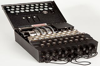
The Enigma machine is a cipher device developed and used in the early- to mid-20th century to protect commercial, diplomatic, and military communication. It was employed extensively by Nazi Germany during World War II, in all branches of the German military. The Enigma machine was considered so secure that it was used to encipher the most top-secret messages.

<span class="mw-page-title-main">Typex</span> British cipher machine

In the history of cryptography, Typex machines were British cipher machines used from 1937. It was an adaptation of the commercial German Enigma with a number of enhancements that greatly increased its security. The cipher machine was used until the mid-1950s when other more modern military encryption systems came into use.

<span class="mw-page-title-main">SIGABA</span> American cipher machine

In the history of cryptography, the ECM Mark II was a cipher machine used by the United States for message encryption from World War II until the 1950s. The machine was also known as the SIGABA or Converter M-134 by the Army, or CSP-888/889 by the Navy, and a modified Navy version was termed the CSP-2900.

<span class="mw-page-title-main">Rotor machine</span>

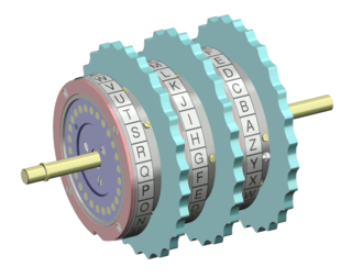
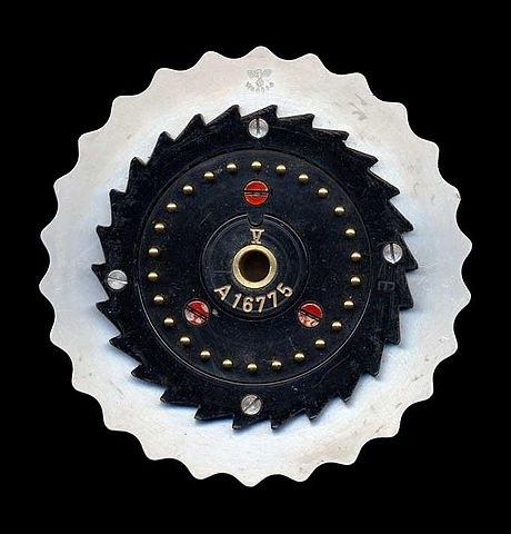
In cryptography, a rotor machine is an electro-mechanical stream cipher device used for encrypting and decrypting messages. Rotor machines were the cryptographic state-of-the-art for much of the 20th century; they were in widespread use in the 1920s–1970s. The most famous example is the German Enigma machine, the output of which was deciphered by the Allies during World War II, producing intelligence code-named Ultra.

<span class="mw-page-title-main">Hans-Thilo Schmidt</span>

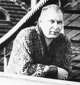
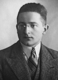
Hans-Thilo Schmidt codenamed Asché or Source D, was a spy who sold secrets about the German Enigma machine to the French during World War II. The materials he provided facilitated Polish mathematician Marian Rejewski's reconstruction of the wiring in the Enigma's rotors and reflector; thereafter the Poles were able to read a large proportion of Enigma-enciphered traffic.

<span class="mw-page-title-main">Bombe</span> Codebreaking device created at Bletchley Park (United Kingdom)

The bombe was an electro-mechanical device used by British cryptologists to help decipher German Enigma-machine-encrypted secret messages during World War II. The US Navy and US Army later produced their own machines to the same functional specification, albeit engineered differently both from each other and from Polish and British bombes.

<i>Bomba</i> (cryptography) Polish decryption device

The bomba, or bomba kryptologiczna, was a special-purpose machine designed around October 1938 by Polish Cipher Bureau cryptologist Marian Rejewski to break German Enigma-machine ciphers.

<span class="mw-page-title-main">M-209</span> Mechanical cipher machine

In cryptography, the M-209, designated CSP-1500 by the United States Navy is a portable, mechanical cipher machine used by the US military primarily in World War II, though it remained in active use through the Korean War. The M-209 was designed by Swedish cryptographer Boris Hagelin in response to a request for such a portable cipher machine, and was an improvement of an earlier machine, the C-36.

<span class="mw-page-title-main">Cryptanalysis of the Enigma</span> Decryption of the cipher of the Enigma machine

Cryptanalysis of the Enigma ciphering system enabled the western Allies in World War II to read substantial amounts of Morse-coded radio communications of the Axis powers that had been enciphered using Enigma machines. This yielded military intelligence which, along with that from other decrypted Axis radio and teleprinter transmissions, was given the codename Ultra.

<span class="mw-page-title-main">KL-7</span> Rotor encryption machine

The TSEC/KL-7, also known as Adonis was an off-line non-reciprocal rotor encryption machine. The KL-7 had rotors to encrypt the text, most of which moved in a complex pattern, controlled by notched rings. The non-moving rotor was fourth from the left of the stack. The KL-7 also encrypted the message indicator.

In the history of cryptography, the NEMA (NEue MAschine) ("new machine"), also designated the T-D (Tasten-Druecker-Maschine) ("key-stroke machine"), was a 10-wheel rotor machine designed by the Swiss Army during the World War II as a replacement for their Enigma machines.

<span class="mw-page-title-main">Fialka</span> Soviet cipher machine

In cryptography, Fialka (M-125) is the name of a Cold War-era Soviet cipher machine. A rotor machine, the device uses 10 rotors, each with 30 contacts along with mechanical pins to control stepping. It also makes use of a punched card mechanism. Fialka means "violet" in Russian. Information regarding the machine was quite scarce until c. 2005 because the device had been kept secret.

Banburismus was a cryptanalytic process developed by Alan Turing at Bletchley Park in Britain during the Second World War. It was used by Bletchley Park's Hut 8 to help break German Kriegsmarine (naval) messages enciphered on Enigma machines. The process used sequential conditional probability to infer information about the likely settings of the Enigma machine. It gave rise to Turing's invention of the ban as a measure of the weight of evidence in favour of a hypothesis. This concept was later applied in Turingery and all the other methods used for breaking the Lorenz cipher.

<span class="mw-page-title-main">Cyclometer</span> Cryptologic device

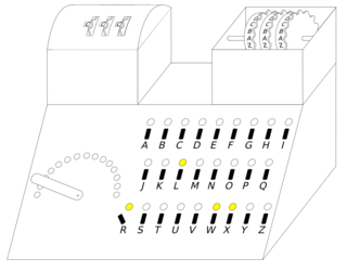
The cyclometer was a cryptologic device designed, "probably in 1934 or 1935," by Marian Rejewski of the Polish Cipher Bureau's German section (BS-4), to catalog the cycle structure of Enigma permutations, thereby facilitating the decryption of German Enigma ciphertext.

In cryptography, the clock was a method devised by Polish mathematician-cryptologist Jerzy Różycki, at the Polish General Staff's Cipher Bureau, to facilitate decrypting German Enigma ciphers. The method determined the rightmost rotor in the German Enigma by exploiting the different turnover positions. For the Poles, learning the rightmost rotor reduced the rotor-order search space by a factor of 3. The British improved the method, and it allowed them to use their limited number of bombes more effectively.

The card catalog, or "catalog of characteristics," in cryptography, was a system designed by Polish Cipher Bureau mathematician-cryptologist Marian Rejewski, and first completed about 1935 or 1936, to facilitate decrypting German Enigma ciphers.

The grill method, in cryptology, was a method used chiefly early on, before the advent of the cyclometer, by the mathematician-cryptologists of the Polish Cipher Bureau in decrypting German Enigma machine ciphers. The Enigma rotor cipher machine changes plaintext characters into cipher text using a different permutation for each character, and so implements a polyalphabetic substitution cipher.

John William Jamieson Herivel was a British science historian and World War II codebreaker at Bletchley Park.

<span class="mw-page-title-main">Marian Rejewski</span> Polish mathematician and cryptologist (1905–1980)

Marian Adam Rejewski was a Polish mathematician and cryptologist who in late 1932 reconstructed the sight-unseen Nazi German military Enigma cipher machine, aided by limited documents obtained by French military intelligence. Over the next nearly seven years, Rejewski and fellow mathematician-cryptologists Jerzy Różycki and Henryk Zygalski developed and used techniques and equipment to decrypt the German machine ciphers, even as the Germans introduced modifications to their equipment and encryption procedures.

The Schlüsselgerät 39 (SG-39) was an electrically operated rotor cipher machine, invented by the German Fritz Menzer during World War II. The device was the evolution of the Enigma rotors coupled with three Hagelin pin wheels to provide variable stepping of the rotors. All three wheels stepped once with each encipherment. Rotors stepped according to normal Enigma rules, except that an active pin at the reading station for a pin wheel prevented the coupled rotor from stepping. The cycle for a normal Enigma was 17,576 characters. When the Schlüsselgerät 39 was correctly configured, its cycle length was characters, which was more than 15,000 times longer than a standard Enigma. The Schlüsselgerät 39 was fully automatic, in that when a key was pressed, the plain and cipher letters were printed on separate paper tapes, divided into five-digit groups. The Schlüsselgerät 39 was abandoned by German forces in favour of the Schlüsselgerät 41.

References

  1. "Enigma wiring". www.cryptomuseum.com. Retrieved 2022-06-09.
  2. 1 2 Mahon 1945 , p. 62