Fast automatic restoration

Last updated

Fast automatic restoration (FASTAR) is an automated fast response system developed and deployed by American Telephone & Telegraph (AT&T) in 1992 for the centralized restoration of its digital transport network. [1] FASTAR automatically reroutes circuits over a spare protection capacity when a fiber-optic cable failure is detected, hence increasing service availability and reducing the impact of the outages in the network. Similar in operation is real-time restoration (RTR), developed and deployed by MCI and used in the MCI network to minimize the effects of a fiber cut. [2]

Contents

Restoration techniques

It is a recovery technique used in computer networks and telecommunication networks such as mesh optical networks, where the backup path (the alternate path that affected traffic takes after a failure condition) and backup channel are computed in real time after the occurrence of a failure. This technique can be broadly classified into two: centralized restoration and distributed restoration. [3]

Centralized restoration techniques

This technique uses a central controller which has access to complete up-to-date and accurate information about the network, the available resources, resources used, the physical topology of the network, the service demands etc. When failure is detected in any part of the network through some failure detection, identification and notification scheme, the central controller calculates a new re-route path around the failure based on the information in its database about the current state of the network. After this new route (backup path) is calculated, the central controller sends out commands to all the affected digital cross-connects to make appropriate reconfigurations to their switching elements in order to implement this new path. FASTAR and RTR restoration systems are examples of systems that use this restoration technique. [3]

Distributed restoration techniques

In this restoration technique, no central controller is used, hence no up-to-date database of the state of the network is needed. In this scheme, all nodes in the network use local controllers that have only local information about how a particular node is connected to its neighboring nodes, available and spare capacity on the links used to connect to neighbors, and the state of their switching elements. When a failure occurs in any part of the network, the local controllers handle the computation and re-routing of the affected traffic. An example of an approach where this technique is used is the Self-Healing Networks (SHN). [3]

Recovery architecture evolution

As the transport networks gradually developed from digital cross connect system (DCS)-based mesh networks, to SONET ring networks, and to optical mesh networks over the years, so did the recovery architecture used therein. The recovery architectures used for the different transport networks are: DCS-based mesh networks restoration of DS3 facilities, Add-Drop Multiplexer (ADM)-based ring protection of SONET ring networks, and finally Optical Cross Connect (OXC)-based mixed protection and restoration of optical mesh networks [4]

DCS-based mesh restoration

The first restoration architecture which was used in the 1980s is the DCS-based mesh restoration of DS3 facilities. This architecture used a centralized restoration technique: every restoration event was coordinated from the network operation center (NOC). This restoration architecture is path-based and failure dependent, and is used after a fault occurs, for fault detection and isolation. This architecture is capacity-efficient due to the use of stub release but has a slow failure recovery time (the time it takes to reestablish traffic continuity after a failure by rerouting the signals on diverse facilities) on the order of minutes. [4]

ADM-based ring protection

This architecture was implemented in the 1990s with the introduction of the SONET/SDH networks, and employed the distributed protection technique. It uses either path-based (UPSR) or span-based (BLSR) protection, and its recovery path is precomputed before the occurrence of a failure. ADM-based ring protection is capacity-inefficient, unlike the DCS-based mesh restoration, but has a faster recovery time (50 ms). [4]

OXC-based protection of optical mesh networks

This recovery architecture is used in the protection of optical mesh networks which was introduced in early 2000s. This protection architecture has a recovery time between tens and hundreds of milliseconds which is a significant improvement over the recovery time supported in DCS-based mesh restoration but unlike the DCS-based mesh restoration, its recovery path is predetermined and pre-provisioned. This architecture also has the capacity efficiency seen in the preceding mesh restoration architecture (DCS-based). [4]

FASTAR architecture

FASTAR uses DCS-based mesh restoration architecture. This architecture consists of nodal equipment, central control equipment, and a data communication network interconnecting the nodes to the central controller. The figure on the right explains the architecture of FASTAR and how the different building blocks interact.

Architecture of FASTAR Architecture of at&t's FASTAR.png
Architecture of FASTAR

Central equipments

The central processor called the Restoration and Provisioning Integrated Design (RAPID) located at the NOC [5] is responsible for receiving and analyzing alarm reports generated in the event of a fiber failure. it also handles alternate (backup) route computation, re-routing of the affected traffic from the primary path to the already computed backup path, path assurance tests, and enables the roll-back of traffic to the original path after the failure is repaired. [6] The RAPID maintains an up-to-date information about the state of the network and the available spare capacity. [7] The Central Access and Display system (CADS) provides a craft interface for RAPID and other related restoration management systems.

The Traffic Maintenance and Administration System (TMAS) enables RAPID to perform and control the protection switch lock-out process on protection channels being used for restoration, by sending commands to the Line Terminating Equipment (LTE).

Nodal equipment

The Restoration Network Controllers (RNCs) are located at each central office (CO) in the fiber optic network. [5] The alarms generated by the affected digital access and cross-connect system (DACSs) or from the LTE are sent to the RNC, where it is aged to find out if the alarm is as a result of a transient, correlated and finally sent to the RAPID via the data communication network.

The LTE, which is either FT Series G digital transmission system or an add drop multiplexer (ADM), reports any fiber failure between LTEs to the RNC and also provides RAPID with immediate access to the backup channels for re-routing of traffic or path assurance tests.

The Restoration Test Equipment (RTE) provides RAPID with the means to perform continuity tests used in path assurance.

The DACS is responsible for reporting fiber failures and node failures that occur within the office to the RNC. [6] In addition, the DACS enables automatic restoration by providing the central processor access to remotely perform cross-connects at the DS-3 level.

Data communication network

The data communication network is used to connect the nodal equipments with the central controller. To achieve the needed availability of this network, full redundancy is used in the form of two totally diverse terrestrial and satellite-based networks. In an event of a major restoration process, one of these networks can support the communication burden in the absence of the other.

Restoration using FASTAR

17-node DS3 transport network with traffic from node A to node Q before failure 17 node mesh network.svg
17-node DS3 transport network with traffic from node A to node Q before failure
Traffic from node A to node Q via C, F, K, and L is rerouted by FASTAR through nodes: C, D and E 17 node network with a single link failure.svg
Traffic from node A to node Q via C, F, K, and L is rerouted by FASTAR through nodes: C, D and E

FASTAR operates at the DS-3 level; it does not restore individual smaller demands. [8] FASTAR restores 90 to 95 percent of the affected DS-3 demand within two to three minutes. [9] When a fiber-optic cut occurs between the output of a DACS equipment and the input of another, each RNC collects alarms from the affected LTEs. The RNC ages these alarms and sends it to RAPID. RAPID determines the amount of spare capacity available after this failure, identifies the DS-3 demands affected, finds the restoration route for each affected traffic in sequential order of priority, and sends a command to the appropriate DACSs to implement the re-route, thus establishing a restoration.

In the figure on the right, a route exists between node A and node Q via nodes C, F, K, and L. In the event of a fiber-optic cable failure between nodes F and K, the LTE (FT Series G or the ADM) in these two offices detects and sends alarm reports for this failure to their respective RNCs. Both RNCs age the alarm and send these reports to RAPID, located at the NOC. RAPID initiates a time window to ensure all related alarms generated from the RNCs of the affected nodes and the RNC of any other office whose traffic uses the F to K failed fiber optic cable. When this window times out, RAPID performs route computation, to establish a new backup path for the traffic between node A and node Q. Here it creates a new route through C, F, G, J, K, and L. This route computation is also done sequentially in order of priority for all the traffic between any two nodes in the network that use the same failed fiber-optic cable. Once the backup path for all the traffic going through nodes F and K has been computed, RAPID ensures that there is continuity or connectivity along the established back-up paths by sending a command to the RNCs located at A and Q, both of which in turn use the test signal generated by their respective RTE to check for continuity in the link. When the connectivity of this backup path has been verified, the traffic between nodes A and Q is transferred to this backup path by commanding the DACS IIIs to make the appropriate cross connections. RAPID performs a service verification test to verify that the service transfer was successful. If this test returns a positive result, then the service transfer was successful, else the service transfer was unsuccessful and needs to be repeated. This service or traffic transfer process is performed for all the traffic going through the affected fiber optic cable F–K. [8] FASTAR restores as much of the affected traffic demand as the available protection capacity will allow.

Restoring networks with SRLGs using FASTAR

Shared Risk Link Groups (SRLGs) refer to situations where links that connect two distinct nodes or offices in a network share a common conduit. In that configuration, links in the group have a shared risk: if one link fails, other links in the group may fail too. Majority of the networks in use today use SRLGs, as most times, the only access into a building or across a bridge is only through a single conduit. To restore the traffic in a link between two offices or nodes that share the same SRLG with other links in the event of a conduit cut, at least one of these two offices must be FASTAR-ompliant. [10]

Example of SRLGs between offices A, B and C Shared Risk Link Groups.png
Example of SRLGs between offices A, B and C
Failure of SRLG2 between office B and C Figure showing SRLG failure between B and C.png
Failure of SRLG2 between office B and C
Failure of SRLG1 between office A and B Figure showing a failure in an SRLG.png
Failure of SRLG1 between office A and B

A cut in SRLG1 would be restorable using FASTAR if FASTAR is implemented in either office A or B but B and C were not yet FASTAR-compliant. But given a failure in SRLG2, the DS-3 traffic on link 3 would be restored by FASTAR via a newly re-computed backup path while the DS-3 traffic on link 2 would not be restored as FASTAR is not implemented in either office B or C. To restore all three links in the event of failure of both SRLGs, FASTAR is implemented in offices A and C. A failure in SRLG1 would cause FASTAR to automatically re-route each of the traffic on link 1 and 3 via two re-computed backup paths. Also if at another time failure of SRLG2 is detected, it is reported to RAPID and the traffic through link 2 and 3 are each re-routed through a new backup path. [10]

FASTAR network management

Overview of the RNC-EMS process and communications RNC-EMS of FASTAR.png
Overview of the RNC-EMS process and communications

FASTAR network management is used to integrate and analyze the different data and alarms supplied by the various system elements that make up the FASTAR architecture for centralized display, and to troubleshoot and isolate problems through fault management analysis so that corrective action can be taken. The FASTAR network management cuts across three tiers. [10]

  1. The first (lowest) tier consists of all the elements that constitute the FASTAR architecture, and all the interconnecting links between them.
  2. The second tier consists of Element Management Systems (EMSs) which are computerized operations systems (OSs) used to manage the elements that are in the first tier. The different EMSs are collectively called FASTAR Element Management Systems (FASTEMS). The two major FASTEMS are the DACS Element Management Systems (DEMS) and the RNC Element Management Systems (RNC-EMS). DEMS is designed to assist NOC with management of DACSs. In the event of a change in the status of the network due to a fiber failure, RAPID forwards this status change to DEMS, which triggers DEMS to isolate the problem. The RNC-EMS monitors the RNCs directly via the data communication network and indirectly monitors the RTE, LTE, and DASC III, and their links to the RNC, via agents residing in the RNC. It consists two components: the manager and the agent. The manager software daemon (NMd) runs on the RNC-EMS machine and is responsible for polling the RNCs. Every RNC is polled twice, once over each of the data communication networks. The agent software daemon (NAd) runs on every RNC as part of the application software. It accesses the RNC application log to respond to manager queries, and has the ability to send autonomous alarms to the manager.
  3. The third (highest) tier comprises only the CADS workstation and provides centralized access to the network manager via the lower two tiers.

See also

Related Research Articles

Synchronous optical networking

Synchronous optical networking (SONET) and synchronous digital hierarchy (SDH) are standardized protocols that transfer multiple digital bit streams synchronously over optical fiber using lasers or highly coherent light from light-emitting diodes (LEDs). At low transmission rates data can also be transferred via an electrical interface. The method was developed to replace the plesiochronous digital hierarchy (PDH) system for transporting large amounts of telephone calls and data traffic over the same fiber without the problems of synchronization.

Network topology Arrangement of the various elements of a computer network; topological structure of a network and may be depicted physically or logically

Network topology is the arrangement of the elements of a communication network. Network topology can be used to define or describe the arrangement of various types of telecommunication networks, including command and control radio networks, industrial fieldbusses and computer networks.

An optical switch is a device that selectively switches optical signals from one channel to another. The switching can be temporal or spatial.The former is known as an optical (time-domain) switch or an optical modulator, while the latter is called an optical space switch or an optical router. In general, optical modulators and routers can be made from each other.

Hybrid fiber-coaxial (HFC) is a telecommunications industry term for a broadband network that combines optical fiber and coaxial cable. It has been commonly employed globally by cable television operators since the early 1990s.

The Radio Network Controller (RNC) is a governing element in the UMTS radio access network (UTRAN) and is responsible for controlling the Node Bs that are connected to it. The RNC carries out radio resource management, some of the mobility management functions and is the point where encryption is done before user data is sent to and from the mobile. The RNC connects to the Circuit Switched Core Network through Media Gateway (MGW) and to the SGSN in the Packet Switched Core Network.

In a hierarchical telecommunications network, the backhaul portion of the network comprises the intermediate links between the core network, or backbone network, and the small subnetworks at the edge of the network.

A digital cross-connect system is a piece of circuit-switched network equipment, used in telecommunications networks, that allows lower-level TDM bit streams, such as DS0 bit streams, to be rearranged and interconnected among higher-level TDM signals, such as DS1 bit streams. DCS units are available that operate on both older T-carrier/E-carrier bit streams, as well as newer SONET/SDH bit streams.

MPLS Fast Reroute is a local restoration network resiliency mechanism. It is actually a feature of resource reservation protocol (RSVP) traffic engineering (RSVP-TE). In MPLS local protection each label switched path (LSP) passing through a facility is protected by a backup path which originates at the node immediately upstream to that facility.

In a telecommunication network, a ring network affords fault tolerance to the network because there are two paths between any two nodes on the network. Ring protection is the system used to assure communication continues in the event of failure of one of the paths. There are two widely used protection architectures: 1+1 protection and 1:1 protection.


In telecommunications, subnetwork connection protection (SNCP), is a type of protection mechanism associated with synchronous optical networks such as synchronous digital hierarchy (SDH).

In telecommunications, radio frequency over glass (RFoG) is a deep-fiber network design in which the coax portion of the hybrid fiber coax (HFC) network is replaced by a single-fiber passive optical network (PON). Downstream and return-path transmission use different wavelengths to share the same fiber. The return-path wavelength standard is expected to be 1610 nm, but early deployments have used 1590 nm. Using 1590/1610 nm for the return path allows the fiber infrastructure to support both RFoG and a standards-based PON simultaneously, operating with 1490 nm downstream and 1310 nm return-path wavelengths.

Optical mesh network

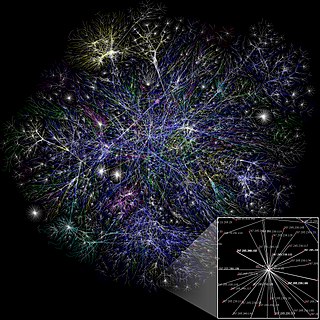
An optical mesh network is a type of optical telecommunications network employing wired fiber-optic communication or wireless free-space optical communication in a mesh network architecture.

Remote radio head

A remote radio head (RRH), also called a remote radio unit (RRU) in wireless networks, is a remote radio transceiver that connects to an operator radio control panel via electrical or wireless interface. When used to describe aircraft radio cockpit radio systems, the control panel is often called the radio head.

E-UTRAN Node B, also known as Evolved Node B, is the element in E-UTRA of LTE that is the evolution of the element Node B in UTRA of UMTS. It is the hardware that is connected to the mobile phone network that communicates directly wirelessly with mobile handsets (UEs), like a base transceiver station (BTS) in GSM networks.

Shared risk resource group is a concept in optical mesh network routing that different networks may suffer from a common failure if they share a common risk or a common SRG. SRG is not limited to Optical mesh networks: SRGs are also used in MPLS, IP networks, and synchronous optical networks.

Multicast lightpaths

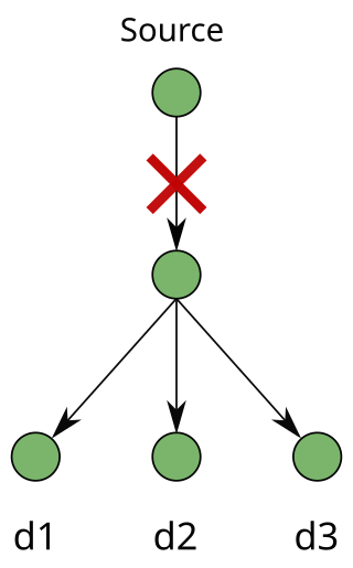
A multicast session requires a "point-to-multipoint" connection from a source node to multiple destination nodes. The source node is known as the root. The destination nodes are known as leaves. In the modern era, it is important to protect multicast connections in an optical mesh network. Recently, multicast applications have gained popularity as they are important to protecting critical sessions against failures such as fiber cuts, hardware faults, and natural disasters.

Link protection is designed to safeguard networks from failure. Failures in high-speed networks have always been a concern of utmos importance. A single fiber cut can lead to heavy losses of traffic and protection-switching techniques have been used as the key source to ensure survivability in networks. Survivability can be addressed in many layers in a network and protection can be performed at the physical layer, Layer 2 and Layer 3 (IP).

Path protection in telecommunications is an end-to-end protection scheme used in connection oriented circuits in different network architectures to protect against inevitable failures on service providers’ network that might affect the services offered to end customers. Any failure occurred at any point along the path of a circuit will cause the end nodes to move/pick the traffic to/from a new route. Finding paths with protection, especially in elastic optical networks, was considered a difficult problem, but an efficient and optimal algorithm was proposed.

Segment protection is a type of backup technique that can be used in most networks. It can be implemented as a dedicated backup or as a shared backup protection. Overlapping segments and non-overlapping segments are allowed; each providing different advantages.

The p-Cycle protection scheme is a technique to protect a mesh network from a failure of a link, with the benefits of ring like recovery speed and mesh-like capacity efficiency, similar to that of a shared backup path protection (SBPP). p-Cycle protection was invented in late 1990s, with research and development done mostly by Wayne D. Grover, and D. Stamatelakis.

References

  1. "Milestones in AT&T Network History". Archived from the original on 2007-01-07. Retrieved 2013-11-23.
  2. Real-Time Restoration
  3. 1 2 3 Path Routing in Mesh Optical Networks", by Eric Bouillet, Georgios Ellinas, Jean-Francois Labourdette, and Ramu Ramamurthy
  4. 1 2 3 4 ""Shared Mesh Restoration in Optical Networks", by Jean-Francois Labourdette" (PDF). Archived from the original (PDF) on 2006-09-10. Retrieved 2013-11-27.
  5. 1 2 Next Generation Transport Networks: Data, Management, and Control Planes by Manohar, N. E.; Steven S. G.; Lakshmi G. R.; Wayne D. G.
  6. 1 2 Chao, C-W; Dollard, P. M.; Weythman, J. E.; Nguyen, L. T.; Eslambolchi, H., "FASTAR-a robust system for fast DS3 restoration," Global Telecommunications Conference, 1991. GLOBECOM '91. 'Countdown to the New Millennium. Featuring a Mini-Theme on: Personal Communications Services , vol., no., pp.1396,1400 vol.2, 2-5 Dec 1991
  7. Optical Fiber Telecommunications IV-B: Systems and Impairments by Ivan Kaminow, Tingye Li
  8. 1 2 Optimizing Restoration Capacity in the AT&T Network by Cwilich S., Deng M. , Houck D.J. , Lynch D.F., Ken, A.,Yan, D.
  9. AT&T Best Practices-Network Continuity Overview
  10. 1 2 3 operations in the real AT&T transport network by Bums H.S., Chao C.W., Dollard P.M., Mallon R.E., Eslambolchi H., Wolfmeyer P.A.

Further reading