
A composite material is a material which is produced from two or more constituent materials. These constituent materials have notably dissimilar chemical or physical properties and are merged to create a material with properties unlike the individual elements. Within the finished structure, the individual elements remain separate and distinct, distinguishing composites from mixtures and solid solutions. Composite materials with more than one distinct layer are called composite laminates.

Young's modulus is a mechanical property of solid materials that measures the tensile or compressive stiffness when the force is applied lengthwise. It is the modulus of elasticity for tension or axial compression. Young's modulus is defined as the ratio of the stress applied to the object and the resulting axial strain in the linear elastic region of the material.
In engineering, deformation refers to the change in size or shape of an object.

In engineering and materials science, a stress–strain curve for a material gives the relationship between stress and strain. It is obtained by gradually applying load to a test coupon and measuring the deformation, from which the stress and strain can be determined. These curves reveal many of the properties of a material, such as the Young's modulus, the yield strength and the ultimate tensile strength.

Fracture is the appearance of a crack or complete separation of an object or material into two or more pieces under the action of stress. The fracture of a solid usually occurs due to the development of certain displacement discontinuity surfaces within the solid. If a displacement develops perpendicular to the surface, it is called a normal tensile crack or simply a crack; if a displacement develops tangentially, it is called a shear crack, slip band, or dislocation.

In mechanics, compressive strength is the capacity of a material or structure to withstand loads tending to reduce size. In other words, compressive strength resists compression, whereas tensile strength resists tension. In the study of strength of materials, tensile strength, compressive strength, and shear strength can be analyzed independently.

In structural engineering, buckling is the sudden change in shape (deformation) of a structural component under load, such as the bowing of a column under compression or the wrinkling of a plate under shear. If a structure is subjected to a gradually increasing load, when the load reaches a critical level, a member may suddenly change shape and the structure and component is said to have buckled. Euler's critical load and Johnson's parabolic formula are used to determine the buckling stress of a column.
In continuum mechanics, the maximum distortion energy criterion states that yielding of a ductile material begins when the second invariant of deviatoric stress reaches a critical value. It is a part of plasticity theory that mostly applies to ductile materials, such as some metals. Prior to yield, material response can be assumed to be of a nonlinear elastic, viscoelastic, or linear elastic behavior.

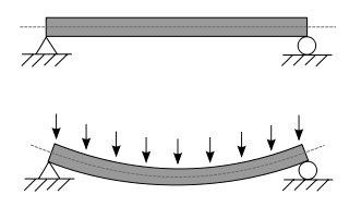
In applied mechanics, bending characterizes the behavior of a slender structural element subjected to an external load applied perpendicularly to a longitudinal axis of the element.

Euler–Bernoulli beam theory is a simplification of the linear theory of elasticity which provides a means of calculating the load-carrying and deflection characteristics of beams. It covers the case corresponding to small deflections of a beam that is subjected to lateral loads only. By ignoring the effects of shear deformation and rotatory inertia, it is thus a special case of Timoshenko–Ehrenfest beam theory. It was first enunciated circa 1750, but was not applied on a large scale until the development of the Eiffel Tower and the Ferris wheel in the late 19th century. Following these successful demonstrations, it quickly became a cornerstone of engineering and an enabler of the Second Industrial Revolution.

Delamination is a mode of failure where a material fractures into layers. A variety of materials, including laminate composites and concrete, can fail by delamination. Processing can create layers in materials, such as steel formed by rolling and plastics and metals from 3D printing which can fail from layer separation. Also, surface coatings, such as paints and films, can delaminate from the coated substrate.

In engineering, shear strength is the strength of a material or component against the type of yield or structural failure when the material or component fails in shear. A shear load is a force that tends to produce a sliding failure on a material along a plane that is parallel to the direction of the force. When a paper is cut with scissors, the paper fails in shear.
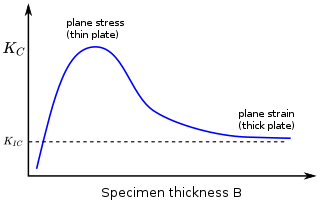
In materials science, fracture toughness is the critical stress intensity factor of a sharp crack where propagation of the crack suddenly becomes rapid and unlimited. A component's thickness affects the constraint conditions at the tip of a crack with thin components having plane stress conditions and thick components having plane strain conditions. Plane strain conditions give the lowest fracture toughness value which is a material property. The critical value of stress intensity factor in mode I loading measured under plane strain conditions is known as the plane strain fracture toughness, denoted . When a test fails to meet the thickness and other test requirements that are in place to ensure plane strain conditions, the fracture toughness value produced is given the designation . Fracture toughness is a quantitative way of expressing a material's resistance to crack propagation and standard values for a given material are generally available.
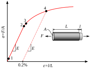
In materials science and engineering, the yield point is the point on a stress-strain curve that indicates the limit of elastic behavior and the beginning of plastic behavior. Below the yield point, a material will deform elastically and will return to its original shape when the applied stress is removed. Once the yield point is passed, some fraction of the deformation will be permanent and non-reversible and is known as plastic deformation.

The three-point bending flexural test provides values for the modulus of elasticity in bending , flexural stress , flexural strain and the flexural stress–strain response of the material. This test is performed on a universal testing machine with a three-point or four-point bend fixture. The main advantage of a three-point flexural test is the ease of the specimen preparation and testing. However, this method has also some disadvantages: the results of the testing method are sensitive to specimen and loading geometry and strain rate.
The neutral axis is an axis in the cross section of a beam or shaft along which there are no longitudinal stresses or strains.

In mechanics, the flexural modulus or bending modulus is an intensive property that is computed as the ratio of stress to strain in flexural deformation, or the tendency for a material to resist bending. It is determined from the slope of a stress-strain curve produced by a flexural test, and uses units of force per area. The flexural modulus defined using the 2-point (cantilever) and 3-point bend tests assumes a linear stress strain response.
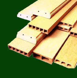
A fiber-reinforced composite (FRC) is a composite building material that consists of three components:
- the fibers as the discontinuous or dispersed phase,
- the matrix as the continuous phase, and
- the fine interphase region, also known as the interface.

According to the classical theories of elastic or plastic structures made from a material with non-random strength (ft), the nominal strength (σN) of a structure is independent of the structure size (D) when geometrically similar structures are considered. Any deviation from this property is called the size effect. For example, conventional strength of materials predicts that a large beam and a tiny beam will fail at the same stress if they are made of the same material. In the real world, because of size effects, a larger beam will fail at a lower stress than a smaller beam.
The four-point flexural test provides values for the modulus of elasticity in bending , flexural stress , flexural strain and the flexural stress-strain response of the material. This test is very similar to the three-point bending flexural test. The major difference being that with the addition of a fourth bearing the portion of the beam between the two loading points is put under maximum stress, as opposed to only the material right under the central bearing in the case of three-point bending.


