
An inductor, also called a coil, choke, or reactor, is a passive two-terminal electrical component that stores energy in a magnetic field when an electric current flows through it. An inductor typically consists of an insulated wire wound into a coil.

In electrical engineering, impedance matching is the practice of designing or adjusting the input impedance or output impedance of an electrical device for a desired value. Often, the desired value is selected to maximize power transfer or minimize signal reflection. For example, impedance matching typically is used to improve power transfer from a radio transmitter via the interconnecting transmission line to the antenna. Signals on a transmission line will be transmitted without reflections if the transmission line is terminated with a matching impedance.

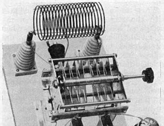
A helical antenna is an antenna consisting of one or more conducting wires wound in the form of a helix. A helical antenna made of one helical wire, the most common type, is called monofilar, while antennas with two or four wires in a helix are called bifilar, or quadrifilar, respectively.

A quartz crystal microbalance (QCM) measures a mass variation per unit area by measuring the change in frequency of a quartz crystal resonator. The resonance is disturbed by the addition or removal of a small mass due to oxide growth/decay or film deposition at the surface of the acoustic resonator. The QCM can be used under vacuum, in gas phase and more recently in liquid environments. It is useful for monitoring the rate of deposition in thin-film deposition systems under vacuum. In liquid, it is highly effective at determining the affinity of molecules to surfaces functionalized with recognition sites. Larger entities such as viruses or polymers are investigated as well. QCM has also been used to investigate interactions between biomolecules. Frequency measurements are easily made to high precision ; hence, it is easy to measure mass densities down to a level of below 1 μg/cm2. In addition to measuring the frequency, the dissipation factor is often measured to help analysis. The dissipation factor is the inverse quality factor of the resonance, Q−1 = w/fr ; it quantifies the damping in the system and is related to the sample's viscoelastic properties.
Thiele/Small parameters are a set of electromechanical parameters that define the specified low frequency performance of a loudspeaker driver. These parameters are published in specification sheets by driver manufacturers so that designers have a guide in selecting off-the-shelf drivers for loudspeaker designs. Using these parameters, a loudspeaker designer may simulate the position, velocity and acceleration of the diaphragm, the input impedance and the sound output of a system comprising a loudspeaker and enclosure. Many of the parameters are strictly defined only at the resonant frequency, but the approach is generally applicable in the frequency range where the diaphragm motion is largely pistonic, i.e., when the entire cone moves in and out as a unit without cone breakup.
In microwave and radio-frequency engineering, a stub or resonant stub is a length of transmission line or waveguide that is connected at one end only. The free end of the stub is either left open-circuit, or short-circuited. Neglecting transmission line losses, the input impedance of the stub is purely reactive; either capacitive or inductive, depending on the electrical length of the stub, and on whether it is open or short circuit. Stubs may thus function as capacitors, inductors and resonant circuits at radio frequencies.

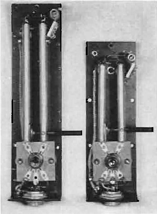
In electronics, a Lecher line or Lecher wires is a pair of parallel wires or rods that were used to measure the wavelength of radio waves, mainly at VHF, UHF and microwave frequencies. They form a short length of balanced transmission line. When attached to a source of radio-frequency power such as a radio transmitter, the radio waves form standing waves along their length. By sliding a conductive bar that bridges the two wires along their length, the length of the waves can be physically measured. Austrian physicist Ernst Lecher, improving on techniques used by Oliver Lodge and Heinrich Hertz, developed this method of measuring wavelength around 1888. Lecher lines were used as frequency measuring devices until inexpensive frequency counters became available after World War 2. They were also used as components, often called "resonant stubs", in VHF, UHF and microwave radio equipment such as transmitters, radar sets, and television sets, serving as tank circuits, filters, and impedance-matching devices. They are used at frequencies between HF/VHF, where lumped components are used, and UHF/SHF, where resonant cavities are more practical.

Prototype filters are electronic filter designs that are used as a template to produce a modified filter design for a particular application. They are an example of a nondimensionalised design from which the desired filter can be scaled or transformed. They are most often seen in regard to electronic filters and especially linear analogue passive filters. However, in principle, the method can be applied to any kind of linear filter or signal processing, including mechanical, acoustic and optical filters.

These filters are electrical wave filters designed using the image method. They are an invention of Otto Zobel at AT&T Corp. They are a generalisation of the m-type filter in that a transform is applied that modifies the transfer function while keeping the image impedance unchanged. For filters that have only one stopband there is no distinction with the m-type filter. However, for a filter that has multiple stopbands, there is the possibility that the form of the transfer function in each stopband can be different. For instance, it may be required to filter one band with the sharpest possible cut-off, but in another to minimise phase distortion while still achieving some attenuation. If the form is identical at each transition from passband to stopband the filter will be the same as an m-type filter. If they are different, then the general case described here pertains.

A microwave cavity or radio frequency cavity is a special type of resonator, consisting of a closed metal structure that confines electromagnetic fields in the microwave or RF region of the spectrum. The structure is either hollow or filled with dielectric material. The microwaves bounce back and forth between the walls of the cavity. At the cavity's resonant frequencies they reinforce to form standing waves in the cavity. Therefore, the cavity functions similarly to an organ pipe or sound box in a musical instrument, oscillating preferentially at a series of frequencies, its resonant frequencies. Thus it can act as a bandpass filter, allowing microwaves of a particular frequency to pass while blocking microwaves at nearby frequencies.
Analogue filters are a basic building block of signal processing much used in electronics. Amongst their many applications are the separation of an audio signal before application to bass, mid-range, and tweeter loudspeakers; the combining and later separation of multiple telephone conversations onto a single channel; the selection of a chosen radio station in a radio receiver and rejection of others.
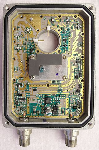
A distributed-element filter is an electronic filter in which capacitance, inductance, and resistance are not localised in discrete capacitors, inductors, and resistors as they are in conventional filters. Its purpose is to allow a range of signal frequencies to pass, but to block others. Conventional filters are constructed from inductors and capacitors, and the circuits so built are described by the lumped element model, which considers each element to be "lumped together" at one place. That model is conceptually simple, but it becomes increasingly unreliable as the frequency of the signal increases, or equivalently as the wavelength decreases. The distributed-element model applies at all frequencies, and is used in transmission-line theory; many distributed-element components are made of short lengths of transmission line. In the distributed view of circuits, the elements are distributed along the length of conductors and are inextricably mixed together. The filter design is usually concerned only with inductance and capacitance, but because of this mixing of elements they cannot be treated as separate "lumped" capacitors and inductors. There is no precise frequency above which distributed element filters must be used but they are especially associated with the microwave band.

A waveguide filter is an electronic filter constructed with waveguide technology. Waveguides are hollow metal conduits inside which an electromagnetic wave may be transmitted. Filters are devices used to allow signals at some frequencies to pass, while others are rejected. Filters are a basic component of electronic engineering designs and have numerous applications. These include selection of signals and limitation of noise. Waveguide filters are most useful in the microwave band of frequencies, where they are a convenient size and have low loss. Examples of microwave filter use are found in satellite communications, telephone networks, and television broadcasting.

A mechanical filter is a signal processing filter usually used in place of an electronic filter at radio frequencies. Its purpose is the same as that of a normal electronic filter: to pass a range of signal frequencies, but to block others. The filter acts on mechanical vibrations which are the analogue of the electrical signal. At the input and output of the filter, transducers convert the electrical signal into, and then back from, these mechanical vibrations.
An RLC circuit is an electrical circuit consisting of a resistor (R), an inductor (L), and a capacitor (C), connected in series or in parallel. The name of the circuit is derived from the letters that are used to denote the constituent components of this circuit, where the sequence of the components may vary from RLC.
Circuit quantum electrodynamics provides a means of studying the fundamental interaction between light and matter. As in the field of cavity quantum electrodynamics, a single photon within a single mode cavity coherently couples to a quantum object (atom). In contrast to cavity QED, the photon is stored in a one-dimensional on-chip resonator and the quantum object is no natural atom but an artificial one. These artificial atoms usually are mesoscopic devices which exhibit an atom-like energy spectrum. The field of circuit QED is a prominent example for quantum information processing and a promising candidate for future quantum computation.
The coupling coefficient of resonators is a dimensionless value that characterizes interaction of two resonators. Coupling coefficients are used in resonator filter theory. Resonators may be both electromagnetic and acoustic. Coupling coefficients together with resonant frequencies and external quality factors of resonators are the generalized parameters of filters. In order to adjust the frequency response of the filter it is sufficient to optimize only these generalized parameters.

An inverted-F antenna is a type of antenna used in wireless communication, mainly at UHF and microwave frequencies. It consists of a monopole antenna running parallel to a ground plane and grounded at one end. The antenna is fed from an intermediate point a distance from the grounded end. The design has two advantages over a simple monopole: the antenna is shorter and more compact, allowing it to be contained within the case of the mobile device, and it can be impedance matched to the feed circuit by the designer, allowing it to radiate power efficiently, without the need for extraneous matching components.

Distributed-element circuits are electrical circuits composed of lengths of transmission lines or other distributed components. These circuits perform the same functions as conventional circuits composed of passive components, such as capacitors, inductors, and transformers. They are used mostly at microwave frequencies, where conventional components are difficult to implement.
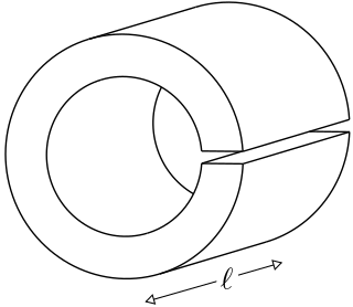
A loop-gap resonator (LGR) is an electromagnetic resonator that operates in the radio and microwave frequency ranges. The simplest LGRs are made from a conducting tube with a narrow slit cut along its length. The LGR dimensions are typically much smaller than the free-space wavelength of the electromagnetic fields at the resonant frequency. Therefore, relatively compact LGRs can be designed to operate at frequencies that are too low to be accessed using, for example, cavity resonators. These structures can have very sharp resonances making them useful for electron spin resonance (ESR) experiments, and precision measurements of electromagnetic material properties.


