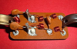
Television signal splitter consisting of a high-pass filter (left) and a low-pass filter (right). The antenna is connected to the screw terminals to the left of center.
Electronic filters are a type of signal processing filter in the form of electrical circuits. This article covers those filters consisting of lumped electronic components, as opposed to distributed-element filters. That is, using components and interconnections that, in analysis, can be considered to exist at a single point. These components can be in discrete packages or part of an integrated circuit.
The most common types of electronic filters are linear filters, regardless of other aspects of their design. See the article on linear filters for details on their design and analysis.
The oldest forms of electronic filters are passive analog linear filters, constructed using only resistors and capacitors or resistors and inductors. These are known as RC and RL single-pole filters respectively. However, these simple filters have very limited uses. Multipole LC filters provide greater control of response form, bandwidth and transition bands. The first of these filters was the constant k filter, invented by George Campbell in 1910. Campbell's filter was a ladder network based on transmission line theory. Together with improved filters by Otto Zobel and others, these filters are known as image parameter filters. A major step forward was taken by Wilhelm Cauer who founded the field of network synthesis around the time of World War II. Cauer's theory allowed filters to be constructed that precisely followed some prescribed frequency function.
Classification by technology
Passive filters
Passive implementations of linear filters are based on combinations of resistors (R), inductors (L) and capacitors (C). These types are collectively known as passive filters, because they do not depend upon an external power supply and they do not contain active components such as transistors.
Inductors block high-frequency signals and conduct low-frequency signals, while capacitors do the reverse. A filter in which the signal passes through an inductor, or in which a capacitor provides a path to ground, presents less attenuation to low-frequency signals than high-frequency signals and is therefore a low-pass filter. If the signal passes through a capacitor, or has a path to ground through an inductor, then the filter presents less attenuation to high-frequency signals than low-frequency signals and therefore is a high-pass filter. Resistors on their own have no frequency-selective properties, but are added to inductors and capacitors to determine the time-constants of the circuit, and therefore the frequencies to which it responds.
The inductors and capacitors are the reactive elements of the filter. The number of elements determines the order of the filter. In this context, an LC tuned circuit being used in a band-pass or band-stop filter is considered a single element even though it consists of two components.
At high frequencies (above about 100 megahertz), sometimes the inductors consist of single loops or strips of sheet metal, and the capacitors consist of adjacent strips of metal. These inductive or capacitive pieces of metal are called stubs.
Single element types
A low-pass electronic filter realised by an RC circuit
The simplest passive filters, RC and RL filters, include only one reactive element, except for the hybrid LC filter, which is characterized by inductance and capacitance integrated in one element.[1]
L filter
An L filter consists of two reactive elements, one in series and one in parallel.
T and π filters
Low-pass π filterHigh-pass T filter
Three-element filters can have a 'T' or 'π' topology and in either geometries, a low-pass, high-pass, band-pass, or band-stop characteristic is possible. The components can be chosen symmetric or not, depending on the required frequency characteristics. The high-pass T filter in the illustration, has a very low impedance at high frequencies, and a very high impedance at low frequencies. That means that it can be inserted in a transmission line, resulting in the high frequencies being passed and low frequencies being reflected. Likewise, for the illustrated low-pass π filter, the circuit can be connected to a transmission line, transmitting low frequencies and reflecting high frequencies. Using m-derived filter sections with correct termination impedances, the input impedance can be reasonably constant in the pass band.[2]
Multiple-element types
Multiple-element filtration are usually constructed as a ladder network. These can be seen as a continuation of the L,T and π designs of filters. More elements are needed when it is desired to improve some parameter of the filter such as stop-band rejection or slope of transition from pass-band to stop-band.
Reflectionless filter
Reflectionless filters are passive structures that in principle have identically zero reflection coefficient at all frequencies. Such structures may be synthesized with lumped inductors, capacitors, and resistors, or by transmission lines and resistors.[3]
Active filters
Active filters are implemented using a combination of passive and active (amplifying) components, and require an outside power source. Operational amplifiers are frequently used in active filter designs. These can have high Q factor, and can achieve resonance without the use of inductors. However, their upper frequency limit is limited by the bandwidth of the amplifiers.
The transfer function of a filter is the ratio of the output signal to that of the input signal as a function of the complex frequency :
.
The transfer function of all linear time-invariant filters, when constructed of lumped components (as opposed to distributed components such as transmission lines), will be the ratio of two polynomials in , i.e. a rational function of . The order of the transfer function will be the highest power of encountered in either the numerator or the denominator.
Classification by topology
Electronic filters can be classified by the technology used to implement them. Filters using passive filter and active filter technology can be further classified by the particular electronic filter topology used to implement them.
Historically, linear analog filter design has evolved through three major approaches. The oldest designs are simple circuits where the main design criterion was the Q factor of the circuit. This reflected the radio receiver application of filtering as Q was a measure of the frequency selectivity of a tuning circuit. From the 1920s filters began to be designed from the image point of view, mostly being driven by the requirements of telecommunications. After World War II the dominant methodology was network synthesis. The higher mathematics used originally required extensive tables of polynomial coefficient values to be published but modern computer resources have made that unnecessary.[4]
Direct circuit analysis
Low order filters can be designed by directly applying basic circuit laws such as Kirchhoff's laws to obtain the transfer function. This kind of analysis is usually only carried out for simple filters of 1st or 2nd order.
This approach analyses the filter sections from the point of view of the filter being in an infinite chain of identical sections. It has the advantages of simplicity of approach and the ability to easily extend to higher orders. It has the disadvantage that accuracy of predicted responses relies on filter terminations in the image impedance, which is usually not the case.[5]
Constant k filter response with 5 elementsZobel network (constant R) filter, 5 sectionsm-derived filter response, m=0.5, 2 elementsm-derived filter response, m=0.5, 5 elements
The network synthesis approach starts with a required transfer function and then expresses that as a polynomial equation of the input impedance of the filter. The actual element values of the filter are obtained by continued-fraction or partial-fraction expansions of this polynomial. Unlike the image method, there is no need for impedance matching networks at the terminations as the effects of the terminating resistors are included in the analysis from the start.[5]
Here is an image comparing Butterworth, Chebyshev, and elliptic filters. The filters in this illustration are all fifth-order low-pass filters. The particular implementation– analog or digital, passive or active– makes no difference; their output would be the same.
As is clear from the image, elliptic filters are sharper than all the others, but they show ripples on the whole bandwidth.
↑Bray, J, Innovation and the Communications Revolution, Institute of Electrical Engineers
12Matthaei, Young, Jones Microwave Filters, Impedance-Matching Networks, and Coupling Structures McGraw-Hill 1964
Zverev, Anatol, I (1969). Handbook of Filter Synthesis. John Wiley & Sons. ISBN0-471-98680-1.{{cite book}}: CS1 maint: multiple names: authors list (link) Catalog of passive filter types and component values. The Bible for practical electronic filter design.
This page is based on this Wikipedia article Text is available under the CC BY-SA 4.0 license; additional terms may apply. Images, videos and audio are available under their respective licenses.