When the current flowing through the coil changes, the time-varying magnetic field induces an electromotive force (emf), or voltage, in the conductor, described by Faraday's law of induction. According to Lenz's law, the induced voltage has a polarity (direction) which opposes the change in current that created it. As a result, inductors oppose any changes in current through them.
An inductor is characterized by its inductance, which is the ratio of the voltage to the rate of change of current. In the International System of Units (SI), the unit of inductance is the henry (H) named for 19th century American scientist Joseph Henry. In the measurement of magnetic circuits, it is equivalent to weber/ampere. Inductors have values that typically range from 1μH (10−6H) to 20H. Many inductors have a magnetic core made of iron or ferrite inside the coil, which serves to increase the magnetic field and thus the inductance. Along with capacitors and resistors, inductors are one of the three passive linearcircuit elements that make up electronic circuits. Inductors are widely used in alternating current (AC) electronic equipment, particularly in radio equipment. They are used to block AC while allowing DC to pass; inductors designed for this purpose are called chokes. They are also used in electronic filters to separate signals of different frequencies, and in combination with capacitors to make tuned circuits, used to tune radio and TV receivers.
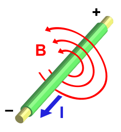
An electric current I creates a magnetic field B around it
An electric current flowing through a conductor generates a magnetic field surrounding it. The magnetic flux linkage generated by a given current depends on the geometric shape of the circuit. Their ratio defines the inductance .[3][4][5][6] Thus
.
The inductance of a circuit depends on the geometry of the current path as well as the magnetic permeability of nearby materials. An inductor is a component consisting of a wire or other conductor shaped to increase the magnetic flux through the circuit, usually in the shape of a coil or helix, with two terminals. Winding the wire into a coil increases the number of times the magnetic fluxlines link the circuit, increasing the field and thus the inductance. The more turns, the higher the inductance. The inductance also depends on the shape of the coil, separation of the turns, and many other factors. By adding a "magnetic core" made of a ferromagnetic material like iron inside the coil, the magnetizing field from the coil will induce magnetization in the material, increasing the magnetic flux. The high permeability of a ferromagnetic core can increase the inductance of a coil by a factor of several thousand over what it would be without it.
Constitutive equation
Any change in the current through an inductor creates a changing flux, inducing a voltage across the inductor. By Faraday's law of induction, the voltage induced by any change in magnetic flux through the circuit is given by[6]
.
Reformulating the definition of L above, we obtain[6]
.
It follows that
if L is independent of time, current and magnetic flux linkage. Thus, inductance is also a measure of the amount of electromotive force (voltage) generated for a given rate of change of current. This is usually taken to be the constitutive relation (defining equation) of the inductor.
Schematic using current's exit terminal as reference for voltage
Because the induced voltage is positive at the current's entrance terminal, the inductor's current–voltage relationship is often expressed without a negative sign by using the current's exit terminal as the reference point for the voltage at the current's entrance terminal (as labeled in the schematic). The current–voltage relationship is then:
The polarity (direction) of the induced voltage is given by Lenz's law, which states that the induced voltage will be such as to oppose the change in current.[7] For example, if the current through an inductor is increasing, the induced potential difference will be positive at the current's entrance point and negative at the exit point, tending to oppose the additional current.[8][9][10] The energy from the external circuit necessary to overcome this potential "hill" is being stored in the magnetic field of the inductor. If the current is decreasing, the induced voltage will be negative at the current's entrance point and positive at the exit point, tending to maintain the current. In this case energy from the magnetic field is being returned to the circuit.
Energy stored in an inductor
One intuitive explanation as to why a potential difference is induced on a change of current in an inductor goes as follows:
When there is a change in current through an inductor there is a change in the strength of the magnetic field. For example, if the current is increased, the magnetic field increases. This, however, does not come without a price. The magnetic field contains potential energy, and increasing the field strength requires more energy to be stored in the field. This energy comes from the electric current through the inductor. The increase in the magnetic potential energy of the field is provided by a corresponding drop in the electric potential energy of the charges flowing through the windings. This appears as a voltage drop across the windings as long as the current increases. Once the current is no longer increased and is held constant, the energy in the magnetic field is constant and no additional energy must be supplied, so the voltage drop across the windings disappears.
Similarly, if the current through the inductor decreases, the magnetic field strength decreases, and the energy in the magnetic field decreases. This energy is returned to the circuit in the form of an increase in the electrical potential energy of the moving charges, causing a voltage rise across the windings.
Derivation
The work done per unit charge on the charges passing through the inductor is . The negative sign indicates that the work is done against the emf, and is not done by the emf. The current is the charge per unit time passing through the inductor. Therefore, the rate of work done by the charges against the emf, that is the rate of change of energy of the current, is given by
From the constitutive equation for the inductor, so
In a ferromagnetic core inductor, when the magnetic field approaches the level at which the core saturates, the inductance will begin to change, it will be a function of the current . Neglecting losses, the energy stored by an inductor with a current passing through it is equal to the amount of work required to establish the current through the inductor:
where is the so-called "differential inductance":
In an air core inductor or a ferromagnetic core inductor below saturation, the inductance is constant (and equal to the differential inductance), so the stored energy is
For inductors with magnetic cores, the above equation is only valid for linear regions of the magnetic flux, at currents below the saturation level of the inductor, where the inductance is approximately constant. Where this is not the case, the integral form must be used with variable.
In the short-time limit, since the current cannot change instantaneously, the initial current is zero. The equivalent circuit of an inductor immediately after the step is applied is an open circuit.
As time passes, the current increases at a constant rate with time until the inductor starts to saturate.
In the long-time limit, the transient response of the inductor will die out, the magnetic flux through the inductor will become constant, so no voltage would be induced between the terminals of the inductor. Therefore, assuming the resistance of the windings is negligible, the equivalent circuit of an inductor a long time after the step is applied is a short circuit.
Ideal and real inductors
The constitutive equation describes the behavior of an ideal inductor with inductance , and without resistance, capacitance, or energy dissipation. In practice, inductors do not follow this theoretical model; real inductors have a measurable resistance due to the resistance of the wire and energy losses in the core, and parasitic capacitance between turns of the wire.[11][12]
A real inductor's capacitive reactance rises with frequency, and at a certain frequency, the inductor will behave as a resonant circuit. Above this self-resonant frequency, the capacitive reactance is the dominant part of the inductor's impedance. At higher frequencies, resistive losses in the windings increase due to the skin effect and proximity effect.
Inductors with ferromagnetic cores experience additional energy losses due to hysteresis and eddy currents in the core, which increase with frequency. At high currents, magnetic core inductors also show sudden departure from ideal behavior due to nonlinearity caused by magnetic saturation of the core.
Inductors radiate electromagnetic energy into surrounding space and may absorb electromagnetic emissions from other circuits, resulting in potential electromagnetic interference.
An early solid-state electrical switching and amplifying device called a saturable reactor exploits saturation of the core as a means of stopping the inductive transfer of current via the core.
Q factor
The winding resistance appears as a resistance in series with the inductor; it is referred to as DCR (DC resistance). This resistance dissipates some of the reactive energy. The quality factor (or Q) of an inductor is the ratio of its inductive reactance to its resistance at a given frequency, and is a measure of its efficiency. The higher the Q factor of the inductor, the closer it approaches the behavior of an ideal inductor. High Q inductors are used with capacitors to make resonant circuits in radio transmitters and receivers. The higher the Q is, the narrower the bandwidth of the resonant circuit.
The Q factor of an inductor is defined as
where is the inductance, is the DC resistance, and the product is the inductive reactance
Q increases linearly with frequency if L and R are constant. Although they are constant at low frequencies, the parameters vary with frequency. For example, skin effect, proximity effect, and core losses increase R with frequency; winding capacitance and variations in permeability with frequency affect L.
At low frequencies and within limits, increasing the number of turns N improves Q because L varies as N2 while R varies linearly with N. Similarly increasing the radius r of an inductor improves (or increases) Q because L varies with r2 while R varies linearly with r. So high Q air core inductors often have large diameters and many turns. Both of those examples assume the diameter of the wire stays the same, so both examples use proportionally more wire. If the total mass of wire is held constant, then there would be no advantage to increasing the number of turns or the radius of the turns because the wire would have to be proportionally thinner.
Using a high permeability ferromagnetic core can greatly increase the inductance for the same amount of copper, so the core can also increase the Q. Cores however also introduce losses that increase with frequency. The core material is chosen for best results for the frequency band. High Q inductors must avoid saturation; one way is by using a (physically larger) air core inductor. At VHF or higher frequencies an air core is likely to be used. A well designed air core inductor may have a Q of several hundred.
Applications
Example of signal filtering. In this configuration, the inductor blocks AC current, while allowing DC current to pass.Example of signal filtering. In this configuration, the inductor decouples DC current, while allowing AC current to pass.
Inductors are used extensively in analog circuits and signal processing. Applications range from the use of large inductors in power supplies, which in conjunction with filter capacitors remove ripple which is a multiple of the mains frequency (or the switching frequency for switched-mode power supplies) from the direct current output, to the small inductance of the ferrite bead or torus installed around a cable to prevent radio frequency interference from being transmitted down the wire.
Inductors are used as the energy storage device in many switched-mode power supplies to produce DC current. The inductor supplies energy to the circuit to keep current flowing during the "off" switching periods and enables topographies where the output voltage is higher than the input voltage.
A tuned circuit, consisting of an inductor connected to a capacitor, acts as a resonator for oscillating current. Tuned circuits are widely used in radio frequency equipment such as radio transmitters and receivers, as narrow bandpass filters to select a single frequency from a composite signal, and in electronic oscillators to generate sinusoidal signals.
Two (or more) inductors in proximity that have coupled magnetic flux (mutual inductance) form a transformer, which is a fundamental component of every electric utilitypower grid. The efficiency of a transformer may decrease as the frequency increases due to eddy currents in the core material and skin effect on the windings. The size of the core can be decreased at higher frequencies. For this reason, aircraft use 400 hertz alternating current rather than the usual 50 or 60 hertz, allowing a great saving in weight from the use of smaller transformers.[13] Transformers enable switched-mode power supplies that galvanically isolate the output from the input.
Inductors are also employed in electrical transmission systems, where they are used to limit switching currents and fault currents. In this field, they are more commonly referred to as reactors.
Inductors have parasitic effects which cause them to depart from ideal behavior. They create and suffer from electromagnetic interference (EMI). Their physical size prevents them from being integrated on semiconductor chips. So the use of inductors is declining in modern electronic devices, particularly compact portable devices. Real inductors are increasingly being replaced by active circuits such as the gyrator which can synthesize inductance using capacitors.
Inductor construction
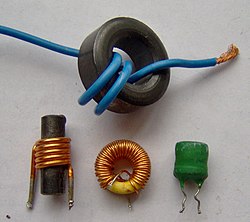
A ferrite core inductor with two 20mH windings.
A ferrite "bead"choke, consisting of an encircling ferrite cylinder, suppresses electronic noise in a computer power cord.
Large 50 Mvarthree-phase iron-core loading inductor at a utility substation
An inductor usually consists of a coil of conducting material, typically insulated copper wire, wrapped around a core either of plastic (to create an air-core inductor) or of a ferromagnetic (or ferrimagnetic) material; the latter is called an "iron core" inductor. The high permeability of the ferromagnetic core increases the magnetic field and confines it closely to the inductor, thereby increasing the inductance. Low frequency inductors are constructed like transformers, with cores of electrical steellaminated to prevent eddy currents. 'Soft' ferrites are widely used for cores above audio frequencies, since they do not cause the large energy losses at high frequencies that ordinary iron alloys do. Inductors come in many shapes. Some inductors have an adjustable core, which enables changing of the inductance. Inductors used to block very high frequencies are sometimes made by stringing a ferrite bead on a wire.
Small inductors can be etched directly onto a printed circuit board by laying out the trace in a spiral pattern. Some such planar inductors use a planar core. Small value inductors can also be built on integrated circuits using the same processes that are used to make interconnects. Aluminium interconnect is typically used, laid out in a spiral coil pattern. However, the small dimensions limit the inductance, and it is far more common to use a circuit called a gyrator that uses a capacitor and active components to behave similarly to an inductor. Regardless of the design, because of the low inductances and low power dissipation on-die inductors allow, they are currently only commercially used for high frequency RF circuits.
Shielded inductors
Inductors used in power regulation systems, lighting, and other systems that require low-noise operating conditions, are often partially or fully shielded.[14][15] In telecommunication circuits employing induction coils and repeating transformers shielding of inductors in close proximity reduces circuit cross-talk.
Types
Air-core inductor
High Q tank coil in tuned circuit of radio transmitter
These coils illustrate high power high Q construction: single layer winding with turns spaced apart to reduce proximity effect losses, made of silver-plated wire or tubing to reduce skin effect losses, supported by narrow insulating strips to reduce dielectric losses
The term air core coil describes an inductor that does not use a magnetic core made of a ferromagnetic material. The term refers to coils wound on plastic, ceramic, or other nonmagnetic forms, as well as those that have only air inside the windings. Air core coils have lower inductance than ferromagnetic core coils, but are often used at high frequencies because they are free from energy losses called core losses that occur in ferromagnetic cores, which increase with frequency. A side effect that can occur in air core coils in which the winding is not rigidly supported on a form is 'microphony': mechanical vibration of the windings can cause variations in the inductance.
Radio-frequency inductor
Collection of RF inductors, showing techniques to reduce losses. The three top left and the ferrite loopstick or rod antenna, bottom, have basket windings.
At high frequencies, particularly radio frequencies (RF), inductors have higher resistance and other losses. In addition to causing power loss, in resonant circuits this can reduce the Q factor of the circuit, broadening the bandwidth. In RF inductors specialized construction techniques are used to minimize these losses. The losses are due to these effects:
Skin effect: The resistance of a wire to high frequency current is higher than its resistance to direct current because of skin effect.[20][21]:p.141 Due to induced eddy currents, radio frequency alternating current does not penetrate far into the body of a conductor but travels along its surface. For example, at 6MHz the skin depth of copper wire is about 0.001 inches (25μm); most of the current is within this depth of the surface. Therefore, in a solid wire, the interior portion of the wire may carry little current, effectively increasing its resistance.
Proximity effect: Another similar effect that also increases the resistance of the wire at high frequencies is proximity effect, which occurs in parallel wires that lie close to each other.[22][21]:p.98 The individual magnetic field of adjacent turns induces eddy currents in the wire of the coil, which causes the current density in the conductor to be displaced away from the adjacent surfaces. Like skin effect, this reduces the effective cross-sectional area of the wire conducting current, increasing its resistance.
Dielectric losses: The high frequency electric field near the conductors in a tank coil can cause the motion of polar molecules in nearby insulating materials, dissipating energy as heat. For this reason, coils used for tuned circuits may be suspended in air, supported by narrow plastic or ceramic strips rather than being wound on coil forms.
Parasitic capacitance: The capacitance between individual wire turns of the coil, called parasitic capacitance, does not cause energy losses but can change the behavior of the coil. Each turn of the coil is at a slightly different potential, so the electric field between neighboring turns stores charge on the wire, so the coil acts as if it has a capacitor in parallel with it. At a high enough frequency this capacitance can resonate with the inductance of the coil forming a tuned circuit, causing the coil to become self-resonant.
(left) Spiderweb coil (right) Adjustable ferrite slug-tuned RF coil with basketweave winding and litz wire
To reduce parasitic capacitance and proximity effect, high Q RF coils are constructed to avoid having many turns lying close together, parallel to one another. The windings of RF coils are often limited to a single layer, and the turns are spaced apart. To reduce resistance due to skin effect, in high-power inductors such as those used in transmitters the windings are sometimes made of a metal strip or tubing which has a larger surface area, and the surface is silver-plated.
Basket-weave coils
To reduce proximity effect and parasitic capacitance, multilayer RF coils are wound in patterns in which successive turns are not parallel but crisscrossed at an angle; these are often called honeycomb or basket-weave coils. These are occasionally wound on a vertical insulating supports with dowels or slots, with the wire weaving in and out through the slots.
Spiderweb coils
Another construction technique with similar advantages is flat spiral coils. These are often wound on a flat insulating support with radial spokes or slots, with the wire weaving in and out through the slots; these are called spiderweb coils. The form has an odd number of slots, so successive turns of the spiral lie on opposite sides of the form, increasing separation.
Litz wire
To reduce skin effect losses, some coils are wound with a special type of radio frequency wire called litz wire. Instead of a single solid conductor, litz wire consists of a number of smaller wire strands that carry the current. Unlike ordinary stranded wire, the strands are insulated from each other, to prevent skin effect from forcing the current to the surface, and are twisted or braided together. The twist pattern ensures that each wire strand spends the same amount of its length on the outside of the wire bundle, so skin effect distributes the current equally between the strands, resulting in a larger cross-sectional conduction area than an equivalent single wire.
Axial Inductor
Small inductors for low current and low power are made in molded cases resembling resistors. These may be either plain (phenolic) core or ferrite core. An ohmmeter readily distinguishes them from similar-sized resistors by showing the low resistance of the inductor.
A variety of types of ferrite core inductors and transformers
Ferromagnetic-core or iron-core inductors use a magnetic core made of a ferromagnetic or ferrimagnetic material such as iron or ferrite to increase the inductance. A magnetic core can increase the inductance of a coil by a factor of several thousand, by increasing the magnetic field due to its higher magnetic permeability. However the magnetic properties of the core material cause several side effects which alter the behavior of the inductor and require special construction:
A time-varying current in a ferromagnetic inductor, which causes a time-varying magnetic field in its core, causes energy losses in the core material that are dissipated as heat, due to two processes:
From Faraday's law of induction, the changing magnetic field can induce circulating loops of electric current in the conductive metal core. The energy in these currents is dissipated as heat in the resistance of the core material. The amount of energy lost increases with the area inside the loop of current.
Changing or reversing the magnetic field in the core also causes losses due to the motion of the tiny magnetic domains it is composed of. The energy loss is proportional to the area of the hysteresis loop in the BH graph of the core material. Materials with low coercivity have narrow hysteresis loops and so low hysteresis losses.
Core loss is non-linear with respect to both frequency of magnetic fluctuation and magnetic flux density. Frequency of magnetic fluctuation is the frequency of AC current in the electric circuit; magnetic flux density corresponds to current in the electric circuit. Magnetic fluctuation gives rise to hysteresis, and magnetic flux density causes eddy currents in the core. These nonlinearities are distinguished from the threshold nonlinearity of saturation. Core loss can be approximately modeled with Steinmetz's equation. At low frequencies and over limited frequency spans (maybe a factor of 10), core loss may be treated as a linear function of frequency with minimal error. However, even in the audio range, nonlinear effects of magnetic core inductors are noticeable and of concern.
Saturation
If the current through a magnetic core coil is high enough that the core saturates, the inductance will fall and current will rise dramatically. This is a nonlinear threshold phenomenon and results in distortion of the signal. For example, audio signals can suffer intermodulation distortion in saturated inductors. To prevent this, in linear circuits the current through iron core inductors must be limited below the saturation level. Some laminated cores have a narrow air gap in them for this purpose, and powdered iron cores have a distributed air gap. This allows higher levels of magnetic flux and thus higher currents through the inductor before it saturates.[23]
Curie point demagnetization
If the temperature of a ferromagnetic or ferrimagnetic core rises to a specified level, the magnetic domains dissociate, and the material becomes paramagnetic, no longer able to support magnetic flux. The inductance falls and current rises dramatically, similarly to what happens during saturation. The effect is reversible: When the temperature falls below the Curie point, magnetic flux resulting from current in the electric circuit will realign the magnetic domains of the core and its magnetic flux will be restored. The Curie point of ferromagnetic materials (iron alloys) is quite high; iron is highest at 770°C. However, for some ferrimagnetic materials (ceramic iron compounds – ferrites) the Curie point can be close to ambient temperatures (below 100°C).[citation needed]
Low-frequency inductors are often made with laminated cores to prevent eddy currents, using construction similar to transformers. The core is made of stacks of thin steel sheets or laminations oriented parallel to the field, with an insulating coating on the surface. The insulation prevents eddy currents between the sheets, so any remaining currents must be within the cross sectional area of the individual laminations, reducing the area of the loop and thus reducing the energy losses greatly. The laminations are made of low-conductivity silicon steel to further reduce eddy current losses.
For higher frequencies, inductors are made with cores of ferrite. Ferrite is a ceramic ferrimagnetic material that is nonconductive, so eddy currents cannot flow within it. The formulation of ferrite is xxFe2O4 where xx represents various metals. For inductor cores soft ferrites are used, which have low coercivity and thus low hysteresis losses.
Another material is powdered iron cemented with a binder. Medium frequency equipment almost exclusively uses powdered iron cores, and inductors and transformers built for the lower shortwaves are made using either cemented powdered iron or ferrites.[citation needed]
Toroidal inductor in the power supply of a wireless router
In an inductor wound on a straight rod-shaped core, the magnetic field lines emerging from one end of the core must pass through the air to re-enter the core at the other end. This reduces the field, because much of the magnetic field path is in air rather than the higher permeability core material and is a source of electromagnetic interference. A higher magnetic field and inductance can be achieved by forming the core in a closed magnetic circuit. The magnetic field lines form closed loops within the core without leaving the core material. The shape often used is a toroidal or doughnut-shaped ferrite core. Because of their symmetry, toroidal cores allow a minimum of the magnetic flux to escape outside the core (called leakage flux), so they radiate less electromagnetic interference than other shapes. Toroidal core coils are manufactured of various materials, primarily ferrite, powdered iron and laminated cores.[24]
Variable inductor
(left) Inductor with a threaded ferrite slug (visible at top) that can be turned to move it into or out of the coil, 4.2cm high. (right) A variometer used in radio receivers in the 1920s
A "roller coil", an adjustable air-core RF inductor used in the tuned circuits of radio transmitters. One of the contacts to the coil is made by the small grooved wheel, which rides on the wire. Turning the shaft rotates the coil, moving the contact wheel up or down the coil, allowing more or fewer turns of the coil into the circuit, to change the inductance.
Probably the most common type of variable inductor today is one with a moveable ferrite magnetic core, which can be slid or screwed in or out of the coil. Moving the core farther into the coil increases the permeability, increasing the magnetic field and the inductance. Many inductors used in radio applications (usually less than 100MHz) use adjustable cores in order to tune such inductors to their desired value, since manufacturing processes have certain tolerances (inaccuracy). Sometimes such cores for frequencies above 100MHz are made from highly conductive non-magnetic material such as aluminium.[25] They decrease the inductance because the magnetic field must bypass them.
Air core inductors can use sliding contacts or multiple taps to increase or decrease the number of turns included in the circuit, to change the inductance. A type much used in the past but mostly obsolete today has a spring contact that can slide along the bare surface of the windings. The disadvantage of this type is that the contact usually short-circuits one or more turns. These turns act like a single-turn short-circuited transformer secondary winding; the large currents induced in them cause power losses.
A type of continuously variable air core inductor is the variometer. This consists of two coils with the same number of turns connected in series, one inside the other. The inner coil is mounted on a shaft so its axis can be turned with respect to the outer coil. When the two coils' axes are collinear, with the magnetic fields pointing in the same direction, the fields add and the inductance is maximum. When the inner coil is turned so its axis is at an angle with the outer, the mutual inductance between them is smaller so the total inductance is less. When the inner coil is turned 180° so the coils are collinear with their magnetic fields opposing, the two fields cancel each other and the inductance is very small. This type has the advantage that it is continuously variable over a wide range. It is used in antenna tuners and matching circuits to match low frequency transmitters to their antennas.
Another method to control the inductance without any moving parts requires an additional DC current bias winding which controls the permeability of an easily saturable core material. SeeMagnetic amplifier.
Choke
An MF or HF radio choke for tenths of an ampere, and a ferrite bead VHF choke for several amperes.
A choke is an inductor designed specifically for blocking high-frequency alternating current (AC) in an electrical circuit, while allowing DC or low-frequency signals to pass. Because the inductor restricts or "chokes" the changes in current, this type of inductor is called a choke. It usually consists of a coil of insulated wire wound on a magnetic core, although some consist of a donut-shaped "bead" of ferrite material strung on a wire. Like other inductors, chokes resist changes in current passing through them increasingly with frequency. The difference between chokes and other inductors is that chokes do not require the high Q factor construction techniques that are used to reduce the resistance in inductors used in tuned circuits.
Circuit analysis
The effect of an inductor in a circuit is to oppose changes in current through it by developing a voltage across it proportional to the rate of change of the current. An ideal inductor would offer no resistance to a constant direct current; however, only superconducting inductors have truly zero electrical resistance.
The relationship between the time-varying voltage v(t) across an inductor with inductance L and the time-varying current i(t) passing through it is described by the differential equation:
When there is a sinusoidalalternating current (AC) through an inductor, a sinusoidal voltage is induced. The amplitude of the voltage is proportional to the product of the amplitude () of the current and the angular frequency () of the current.
In this situation, the phase of the current lags that of the voltage by π/2 (90°). For sinusoids, as the voltage across the inductor goes to its maximum value, the current goes to zero, and as the voltage across the inductor goes to zero, the current through it goes to its maximum value.
If an inductor is connected to a direct current source with value I via a resistance R (at least the DCR of the inductor), and then the current source is short-circuited, the differential relationship above shows that the current through the inductor will discharge with an exponential decay:
Reactance
The ratio of the peak voltage to the peak current in an inductor energised from an AC source is called the reactance and is denoted XL.
Reactance is measured in ohms but referred to as impedance rather than resistance; energy is stored in the magnetic field as current rises and discharged as current falls. Inductive reactance is proportional to frequency. At low frequency the reactance falls; at DC, the inductor behaves as a short circuit. As frequency increases the reactance increases and at a sufficiently high frequency the reactance approaches that of an open circuit.
Corner frequency
In filtering applications, with respect to a particular load impedance, an inductor has a corner frequency defined as:
Laplace circuit analysis (s-domain)
When using the Laplace transform in circuit analysis, the impedance of an ideal inductor with no initial current is represented in the s domain by:
where
is the inductance, and
is the complex frequency.
If the inductor does have initial current, it can be represented by:
adding a voltage source in series with the inductor, having the value:
where
is the inductance, and
is the initial current in the inductor.
(The source should have a polarity that is aligned with the initial current.)
or by adding a current source in parallel with the inductor, having the value:
Inductors in a parallel configuration each have the same potential difference (voltage). To find their total equivalent inductance (Leqv):
The current through inductors in series stays the same, but the voltage across each inductor can be different. The sum of the potential differences (voltage) is equal to the total voltage. To find their total inductance:
These simple relationships hold true only when there is no mutual coupling of magnetic fields between individual inductors.
Mutual inductance
Mutual inductance occurs when the magnetic field of an inductor induces a magnetic field in an adjacent inductor. Mutual induction is the basis of transformer construction.
where M as shown is the maximum possible mutual inductance between 2inductors and L1 and L2 are the two inductors. Hovever, in general
as only a fraction of self flux is linked with the other. This fraction is called "coefficient of flux linkage" () or "coupling coefficient" (with ).
The term C gives the internal inductance of the wire with skin-effect correction (the imaginary part of the internal impedance of the wire). If ω = 0 (DC) then and as ω approaches ∞ , C approaches 0.[29]
↑Nagaoka's coefficient (K) is approximately 1 for a coil which is much longer than its diameter and is tightly wound using small gauge wire (so that it approximates a current sheet).
References
↑Alexander, Charles K.; Sadiku, Matthew N. O. (2013). Fundamentals of Electric Circuits (5ed.). McGraw-Hill. p.226. ISBN978-0-07-338057-5.
↑Urbanitzky, Alfred Ritter von (1886). Electricity in the Service of Man. Macmillan and Company. p.195.
↑Wheeler, H.A. (October 1928). "Simple Inductance Formulas for Radio Coils". Proceedings of the Institute of Radio Engineers. 16 (10): 1398. doi:10.1109/JRPROC.1928.221309. S2CID51638679.
This page is based on this Wikipedia article Text is available under the CC BY-SA 4.0 license; additional terms may apply. Images, videos and audio are available under their respective licenses.