Passivity is a property of engineering systems, most commonly encountered in analog electronics and control systems. Typically, analog designers use passivity to refer to incrementally passive components and systems, which are incapable of power gain. In contrast, control systems engineers will use passivity to refer to thermodynamically passive ones, which consume, but do not produce, energy. As such, without context or a qualifier, the term passive is ambiguous.
An electronic circuit consisting entirely of passive components is called a passive circuit, and has the same properties as a passive component.
If a device is not passive, then it is an active device.
Thermodynamic passivity
In control systems and circuit network theory, a passive component or circuit is one that consumes energy, but does not produce energy. Under this methodology, voltage and current sources are considered active, while resistors, capacitors, inductors, transistors, tunnel diodes, metamaterials and other dissipative and energy-neutral components are considered passive. Circuit designers will sometimes refer to this class of components as dissipative, or thermodynamically passive.
While many books give definitions for passivity, many of these contain subtle errors in how initial conditions are treated and, occasionally, the definitions do not generalize to all types of nonlinear time-varying systems with memory. Below is a correct, formal definition, taken from Wyatt et al.,[1] which also explains the problems with many other definitions. Given an n-portR with a state representation S, and initial state x, define available energy EA as:
where the notation supx→T≥0 indicates that the supremum is taken over all T≥0 and all admissible pairs {v(·),i(·)} with the fixed initial statex (e.g., all voltage–current trajectories for a given initial condition of the system). A system is considered passive if EA is finite for all initial statesx. Otherwise, the system is considered active. Roughly speaking, the inner product is the instantaneous power (e.g., the product of voltage and current), and EA is the upper bound on the integral of the instantaneous power (i.e., energy). This upper bound (taken over all T≥0) is the available energy in the system for the particular initial condition x. If, for all possible initial states of the system, the energy available is finite, then the system is called passive. If the available energy is finite, it is known to be non-negative, since any trajectory with voltage gives an integral equal to zero, and the available energy is the supremum over all possible trajectories. Moreover, by definition, for any trajectory {v(·),i(·)}, the following inequality holds:
.
The existence of a non-negative function EA that satisfies this inequality, known as a "storage function", is equivalent to passivity.[2] For a given system with a known model, it is often easier to construct a storage function satisfying the differential inequality than directly computing the available energy, as taking the supremum on a collection of trajectories might require the use of calculus of variations.
To give other terminology, systems for which the small-signal model is not passive are sometimes called locally active (e.g., transistors and tunnel diodes). Systems that can generate power about a time-variant unperturbed state are often called parametrically active (e.g., certain types of nonlinear capacitors).[4]
Formally, for a memoryless two-terminal element, this means that the current–voltage characteristic is monotonically increasing. For this reason, control systems and circuit network theorists refer to these devices as locally passive, incrementally passive, increasing, monotone increasing, or monotonic. It is not clear how this definition would be formalized to multiport devices with memory – as a practical matter, circuit designers use this term informally, so it may not be necessary to formalize it.[nb 1][5]
Other definitions of passivity
This term is used colloquially in a number of other contexts:
A passive USB to PS/2 adapter consists of wires, and potentially resistors and similar passive (in both the incremental and thermodynamic sense) components. An active USB to PS/2 adapter consists of logic to translate signals (active in the incremental sense)
A passive mixer consists of just resistors (incrementally passive), whereas an active mixer includes components capable of gain (active).
In audio work one can also find both (incrementally) passive and active converters between balanced and unbalanced lines. A passive balun converter is generally just a transformer along with, of course, the requisite connectors, while an active one typically consists of a differential drive or an instrumentation amplifier.
In some books, devices that exhibit gain or a rectifying function (e.g., diodes) are considered active. Only resistors, capacitors, inductors, transformers, and gyrators are considered passive.[6][7][8]United States Patent and Trademark Office is amongst the organisations classifying diodes as active devices.[9] This definition is somewhat informal, as diodes can be considered non-linear resistors, and virtually all real-world devices exhibit some non-linearity.
Sales and product catalogs will often use different informal definitions of this term, as fitting to a particular hierarchy of products being sold. It is not uncommon, for example, to list all silicon devices under "active devices," even if some of those devices are technically passive.
Stability
Passivity, in most cases, can be used to demonstrate that passive circuits will be stable under specific criteria. This only works if only one of the above definitions of passivity is used – if components from the two are mixed, the systems may be unstable under any criteria. In addition, passive circuits will not necessarily be stable under all stability criteria. For instance, a resonant series LC circuit will have unbounded voltage output for a bounded voltage input, but will be stable in the sense of Lyapunov, and given bounded energy input, will have bounded energy output.
Passivity is frequently used in control systems to design stable control systems or to show stability in control systems. This is especially important in the design of large, complex control systems (e.g. stability of airplanes). Passivity is also used in some areas of circuit design, especially filter design.
Passive filter
A passive filter is a kind of electronic filter that is made only from passive components – in contrast to an active filter, it does not require an external power source (beyond the signal). Since most filters are linear, in most cases, passive filters are composed of just the four basic linear elements – resistors, capacitors, inductors, and transformers. More complex passive filters may involve nonlinear elements or more complex linear elements, such as transmission lines.
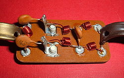
Television signal splitter consisting of a passive high-pass filter (left) and a passive low-pass filter (right). The antenna is connected to the screw terminals to the left of center.
A passive filter has several advantages over an active filter:
Guaranteed stability
Scale better to large signals (tens of amperes, hundreds of volts), where active devices are often expensive or impractical
No power supply needed
Often less expensive in discrete designs (unless large coils are required). Active filters tend to be less expensive in integrated designs.
For linear filters, potentially greater linearity depending on components required (in many cases, active filters allow the use of more linear components; e.g. active components can permit the use of a polypropylene or NP0 ceramic capacitor, while a passive one might require an electrolytic).
They are commonly used in speaker crossover design (due to the moderately large voltages and currents, and the lack of easy access to a power supply), filters in electric power distribution networks (due to the large voltages and currents), power supply bypassing (due to low cost, and in some cases, power requirements), as well as a variety of discrete and home brew circuits (for low-cost and simplicity). Passive filters are uncommon in monolithic integrated circuit design, where active devices are inexpensive compared to resistors and capacitors, and inductors are prohibitively expensive. Passive filters are still found, however, in hybrid integrated circuits. Indeed, it may be the desire to incorporate a passive filter that leads the designer to use the hybrid format.
Energic and non-energic passive circuit elements
Passive circuit elements may be divided into energic and non-energic kinds. When current passes through it, an energic passive circuit element converts some of the energy supplied to it into heat. It is dissipative. When current passes through it, a non-energic passive circuit element converts none of the energy supplied to it into heat. It is non-dissipative. Resistors are energic. Ideal capacitors, inductors, transformers, and gyrators are non-energic.[10]
Notes
↑This is probably formalized in one of the extensions to Duffin's Theorem. One of the extensions may state that if the small signal model is thermodynamically passive, under some conditions, the overall system will be incrementally passive, and therefore, stable. This needs to be verified.
↑Tellegen's Theorem and Electrical Networks. Penfield, Spence, and Duinker. MIT Press, 1970. pg 24-25.
↑Loría, Antonio; Nijmeijer, Henk. "Passivity based control"(PDF). Control Systems, Robotics, and Automation. Vol.XIII. Encyclopedia of Life Support Systems. Retrieved 6 July 2022.
↑E C Young, "passive", The New Penguin Dictionary of Electronics, 2nd ed, p. 400, Penguin Books ISBN0-14-051187-3.
↑Louis E. Frenzel, Crash Course in Electronics Technology, p. 140, Newnes, 1997 ISBN9780750697101.
↑Ian Hickman, Analog Electronics, p. 46, Elsevier, 1999 ISBN9780080493862.
↑Nordholt, E.H. (1983). Design of High-Performance Negative Feedback Amplifiers, Elsevier Scientific Publishing Company, Amsterdam, ISBN0 444 42140 8, p. 15.
Further reading
Khalil, Hassan (2001). Nonlinear Systems (3rded.). Prentice Hall. ISBN0-13-067389-7.—Very readable introductory discussion on passivity in control systems.
Chua, Leon; Desoer, Charles; Kuh, Ernest (1987). Linear and Nonlinear Circuits. McGraw–Hill Companies. ISBN0-07-010898-6.—Good collection of passive stability theorems, but restricted to memoryless one-ports. Readable and formal.
Desoer, Charles; Kuh, Ernest (1969). Basic Circuit Theory. McGraw–Hill Education. ISBN0-07-085183-2.—Somewhat less readable than Chua, and more limited in scope and formality of theorems.
Cruz, Jose; Van Valkenberg, M.E. (1974). Signals in Linear Circuits. Houghton Mifflin. ISBN0-395-16971-2.—Gives a definition of passivity for multiports (in contrast to the above), but the overall discussion of passivity is quite limited.
Wyatt, J.L.; Chua, L.O.; Gannett, J.; Göknar, I.C.; Green, D. (1978). Foundations of Nonlinear Network Theory, Part I: Passivity. Memorandum UCB/ERL M78/76, Electronics Research Laboratory, University of California, Berkeley. Wyatt, J.L.; Chua, L.O.; Gannett, J.; Göknar, I.C.; Green, D. (1980). Foundations of Nonlinear Network Theory, Part II: Losslessness. Memorandum UCB/ERL M80/3, Electronics Research Laboratory, University of California, Berkeley. — A pair of memos that have good discussions of passivity.
Brogliato, Bernard; Lozano, Rogelio; Maschke, Bernhard; Egeland, Olav (2007). Dissipative Systems: Analysis and Control, 2nd edition. Springer Verlag London. ISBN978-1-84628-516-5.—A complete exposition of dissipative systems, with emphasis on the celebrated KYP Lemma, and on Willems' dissipativity and its use in Control.
This page is based on this Wikipedia article Text is available under the CC BY-SA 4.0 license; additional terms may apply. Images, videos and audio are available under their respective licenses.