Gain (electronics)

Last updated

In electronics, gain is a measure of the ability of a two-port circuit (often an amplifier) to increase the power or amplitude of a signal from the input to the output port [1] [2] [3] [4] by adding energy converted from some power supply to the signal. It is usually defined as the mean ratio of the signal amplitude or power at the output port to the amplitude or power at the input port. [1] It is often expressed using the logarithmic decibel (dB) units ("dB gain"). [4] A gain greater than one (greater than zero dB), that is, amplification, is the defining property of an active component or circuit, while a passive circuit will have a gain of less than one. [4]

Contents

The term gain alone is ambiguous, and can refer to the ratio of output to input voltage (voltage gain), current (current gain) or electric power (power gain). [4] In the field of audio and general purpose amplifiers, especially operational amplifiers, the term usually refers to voltage gain, [2] but in radio frequency amplifiers it usually refers to power gain. Furthermore, the term gain is also applied in systems such as sensors where the input and output have different units; in such cases the gain units must be specified, as in "5 microvolts per photon" for the responsivity of a photosensor. The "gain" of a bipolar transistor normally refers to forward current transfer ratio, either hFE ("beta", the static ratio of Ic divided by Ib at some operating point), or sometimes hfe (the small-signal current gain, the slope of the graph of Ic against Ib at a point).

The gain of an electronic device or circuit generally varies with the frequency of the applied signal. Unless otherwise stated, the term refers to the gain for frequencies in the passband, the intended operating frequency range of the equipment. The term gain has a different meaning in antenna design; antenna gain is the ratio of radiation intensity from a directional antenna to (mean radiation intensity from a lossless antenna).

Graph of the input
v
i
(
t
)
{\displaystyle v_{i}(t)}
(blue) and output voltage
v
o
(
t
)
{\displaystyle v_{o}(t)}
(red) of an ideal linear amplifier with a voltage gain of 3 with an arbitrary input signal. At any instant the output voltage is three times the input voltage. Amplification2.svg
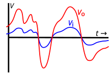
Graph of the input (blue) and output voltage (red) of an ideal linear amplifier with a voltage gain of 3 with an arbitrary input signal. At any instant the output voltage is three times the input voltage.

Logarithmic units and decibels

Power gain

Power gain, in decibels (dB), is defined as follows:

where is the power applied to the input, is the power from the output.

A similar calculation can be done using a natural logarithm instead of a decimal logarithm, resulting in nepers instead of decibels:

Voltage gain

The power gain can be calculated using voltage instead of power using Joule's first law ; the formula is:

In many cases, the input impedance and output impedance are equal, so the above equation can be simplified to:

This simplified formula, the 20 log rule, is used to calculate a voltage gain in decibels and is equivalent to a power gain if and only if the impedances at input and output are equal.

Current gain

In the same way, when power gain is calculated using current instead of power, making the substitution , the formula is:

In many cases, the input and output impedances are equal, so the above equation can be simplified to:

This simplified formula is used to calculate a current gain in decibels and is equivalent to the power gain if and only if the impedances at input and output are equal.

The "current gain" of a bipolar transistor, or , is normally given as a dimensionless number, the ratio of to (or slope of the -versus- graph, for ).

In the cases above, gain will be a dimensionless quantity, as it is the ratio of like units (decibels are not used as units, but rather as a method of indicating a logarithmic relationship). In the bipolar transistor example, it is the ratio of the output current to the input current, both measured in amperes. In the case of other devices, the gain will have a value in SI units. Such is the case with the operational transconductance amplifier, which has an open-loop gain (transconductance) in siemens (mhos), because the gain is a ratio of the output current to the input voltage.

Example

Q. An amplifier has an input impedance of 50 ohms and drives a load of 50 ohms. When its input () is 1 volt, its output () is 10 volts. What is its voltage and power gain?

A. Voltage gain is simply:

The units V/V are optional but make it clear that this figure is a voltage gain and not a power gain. Using the expression for power, P = V2/R, the power gain is:

Again, the units W/W are optional. Power gain is more usually expressed in decibels, thus:

Unity gain

A gain of factor 1 (equivalent to 0 dB) where both input and output are at the same voltage level and impedance is also known as unity gain.

See also

Related Research Articles

The decibel is a relative unit of measurement equal to one tenth of a bel (B). It expresses the ratio of two values of a power or root-power quantity on a logarithmic scale. Two signals whose levels differ by one decibel have a power ratio of 101/10 or root-power ratio of 10120.

<span class="mw-page-title-main">Operational amplifier</span> High-gain voltage amplifier with a differential input

An operational amplifier is a DC-coupled high-gain electronic voltage amplifier with a differential input and, usually, a single-ended output. In this configuration, an op amp produces an output potential that is typically 100,000 times larger than the potential difference between its input terminals. The operational amplifier traces its origin and name to analog computers, where they were used to perform mathematical operations in linear, non-linear, and frequency-dependent circuits.

Noise figure (NF) and noise factor (F) are figures of merit that indicate degradation of the signal-to-noise ratio (SNR) that is caused by components in a signal chain. These figures of merit are used to evaluate the performance of an amplifier or a radio receiver, with lower values indicating better performance.

In electronics, noise temperature is one way of expressing the level of available noise power introduced by a component or source. The power spectral density of the noise is expressed in terms of the temperature that would produce that level of Johnson–Nyquist noise, thus:

<span class="mw-page-title-main">Gain (antenna)</span> Telecommunications performance metric

In electromagnetics, an antenna's gain is a key performance parameter which combines the antenna's directivity and radiation efficiency. The term power gain has been deprecated by IEEE. In a transmitting antenna, the gain describes how well the antenna converts input power into radio waves headed in a specified direction. In a receiving antenna, the gain describes how well the antenna converts radio waves arriving from a specified direction into electrical power. When no direction is specified, gain is understood to refer to the peak value of the gain, the gain in the direction of the antenna's main lobe. A plot of the gain as a function of direction is called the antenna pattern or radiation pattern. It is not to be confused with directivity, which does not take an antenna's radiation efficiency into account.

<span class="mw-page-title-main">Negative-feedback amplifier</span> Type of electronic amplifier

A negative-feedback amplifier is an electronic amplifier that subtracts a fraction of its output from its input, so that negative feedback opposes the original signal. The applied negative feedback can improve its performance and reduces sensitivity to parameter variations due to manufacturing or environment. Because of these advantages, many amplifiers and control systems use negative feedback.

<span class="mw-page-title-main">Differential amplifier</span> Electrical circuit component which amplifies the difference of two analog signals

A differential amplifier is a type of electronic amplifier that amplifies the difference between two input voltages but suppresses any voltage common to the two inputs. It is an analog circuit with two inputs and and one output , in which the output is ideally proportional to the difference between the two voltages:

<span class="mw-page-title-main">Common emitter</span> Type of electronic amplifier using a bipolar junction transistor

In electronics, a common-emitter amplifier is one of three basic single-stage bipolar-junction-transistor (BJT) amplifier topologies, typically used as a voltage amplifier. It offers high current gain, medium input resistance and a high output resistance. The output of a common emitter amplifier is inverted; i.e. for a sine wave input signal, the output signal is 180 degrees out of phase with respect to the input.

<span class="mw-page-title-main">Common collector</span>

In electronics, a common collector amplifier is one of three basic single-stage bipolar junction transistor (BJT) amplifier topologies, typically used as a voltage buffer.

Transconductance, also infrequently called mutual conductance, is the electrical characteristic relating the current through the output of a device to the voltage across the input of a device. Conductance is the reciprocal of resistance.

<span class="mw-page-title-main">Current source</span> Electronic circuit which delivers or absorbs electric current regardless of voltage

A current source is an electronic circuit that delivers or absorbs an electric current which is independent of the voltage across it.

In electronics, the common mode rejection ratio (CMRR) of a differential amplifier is a metric used to quantify the ability of the device to reject common-mode signals, i.e. those that appear simultaneously and in-phase on both inputs. An ideal differential amplifier would have infinite CMRR, however this is not achievable in practice. A high CMRR is required when a differential signal must be amplified in the presence of a possibly large common-mode input, such as strong electromagnetic interference (EMI). An example is audio transmission over balanced line in sound reinforcement or recording.

Scattering parameters or S-parameters describe the electrical behavior of linear electrical networks when undergoing various steady state stimuli by electrical signals.

This article illustrates some typical operational amplifier applications. A non-ideal operational amplifier's equivalent circuit has a finite input impedance, a non-zero output impedance, and a finite gain. A real op-amp has a number of non-ideal features as shown in the diagram, but here a simplified schematic notation is used, many details such as device selection and power supply connections are not shown. Operational amplifiers are optimised for use with negative feedback, and this article discusses only negative-feedback applications. When positive feedback is required, a comparator is usually more appropriate. See Comparator applications for further information.

<span class="mw-page-title-main">Current divider</span> Simple linear circuit

In electronics, a current divider is a simple linear circuit that produces an output current (IX) that is a fraction of its input current (IT). Current division refers to the splitting of current between the branches of the divider. The currents in the various branches of such a circuit will always divide in such a way as to minimize the total energy expended.

<span class="mw-page-title-main">Attenuator (electronics)</span> Type of electronic component

An attenuator is an electronic device that reduces the power of a signal without appreciably distorting its waveform.

A Wilson current mirror is a three-terminal circuit that accepts an input current at the input terminal and provides a "mirrored" current source or sink output at the output terminal. The mirrored current is a precise copy of the input current. It may be used as a Wilson current source by applying a constant bias current to the input branch as in Fig. 2. The circuit is named after George R. Wilson, an integrated circuit design engineer who worked for Tektronix. Wilson devised this configuration in 1967 when he and Barrie Gilbert challenged each other to find an improved current mirror overnight that would use only three transistors. Wilson won the challenge.

In electronic systems, power supply rejection ratio (PSRR), also supply-voltage rejection ratio, is a term widely used to describe the capability of an electronic circuit to suppress any power supply variations to its output signal.

Mismatch loss in transmission line theory is the amount of power expressed in decibels that will not be available on the output due to impedance mismatches and signal reflections. A transmission line that is properly terminated, that is, terminated with the same impedance as that of the characteristic impedance of the transmission line, will have no reflections and therefore no mismatch loss. Mismatch loss represents the amount of power wasted in the system. It can also be thought of as the amount of power gained if the system was perfectly matched. Impedance matching is an important part of RF system design; however, in practice there will likely be some degree of mismatch loss. In real systems, relatively little loss is due to mismatch loss and is often on the order of 1dB. According to Walter Maxwell mismatch does not result in any loss, except through the transmission line. This is because the signal reflected from the load is transmitted back to the source, where it is re-reflected due to the reactive impedance presented by the source, back to the load, until all of the signal's power is emitted or absorbed by the load.

An RF chain is a cascade of electronic components and sub-units which may include amplifiers, filters, mixers, attenuators and detectors. It can take many forms, for example, as a wide-band receiver-detector for electronic warfare (EW) applications, as a tunable narrow-band receiver for communications purposes, as a repeater in signal distribution systems, or as an amplifier and up-converters for a transmitter-driver. In this article, the term RF covers the frequency range "Medium Frequencies" up to "Microwave Frequencies", i.e. from 100 kHz to 20 GHz.

References

  1. 1 2 Graf, Rudolf F. (1999). Modern Dictionary of Electronics (7 ed.). Newnes. p. 314. ISBN   0080511988.
  2. 1 2 Basu, Dipak (2000). Dictionary of Pure and Applied Physics. CRC Press. p. 157. ISBN   1420050222.
  3. Bahl, Inder (2009). Fundamentals of RF and Microwave Transistor Amplifiers. John Wiley and Sons. p. 34. ISBN   978-0470462317.
  4. 1 2 3 4 White, Glenn; Louie, Gary J (2005). The Audio Dictionary (3 ed.). University of Washington Press. p. 18. ISBN   0295984988.