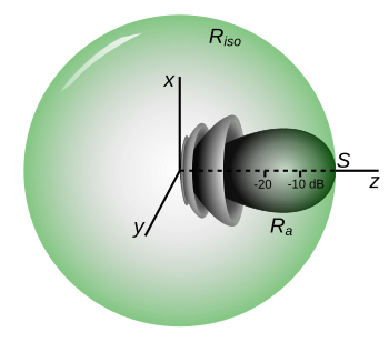
Illustration of definition of effective isotropically radiated power (EIRP). The axes have units of signal strength in decibels. is the radiation pattern of a given transmitter driving a directional antenna, emitting a beam of radio waves along the z axis. It radiates a far field signal strength of in its direction of maximum radiation (main lobe) along the z-axis. The green sphere is the radiation pattern of an ideal isotropic antenna that radiates the same maximum signal strength as the directive antenna does. The transmitter power that would have to be applied to the isotropic antenna to radiate this much power is the EIRP.
Effective radiated power (ERP), synonymous with equivalent radiated power, is an IEEE standardized definition of directional radio frequency (RF) power, such as that emitted by a radio transmitter. It is the total power in watts that would have to be radiated by a half-wave dipole antenna to give the same radiation intensity (signal strength or power flux density in watts per square meter) as the actual source antenna at a distant receiver located in the direction of the antenna's strongest beam (main lobe). ERP measures the combination of the power emitted by the transmitter and the ability of the antenna to direct that power in a given direction. It is equal to the input power to the antenna multiplied by the gain of the antenna. It is used in electronics and telecommunications, particularly in broadcasting to quantify the apparent power of a broadcasting station experienced by listeners in its reception area.
An alternate parameter that measures the same thing is effective isotropic radiated power (EIRP). Effective isotropic radiated power is the hypothetical power that would have to be radiated by an isotropic antenna to give the same ("equivalent") signal strength as the actual source antenna in the direction of the antenna's strongest beam. The difference between EIRP and ERP is that ERP compares the actual antenna to a half-wave dipole antenna, while EIRP compares it to a theoretical isotropic antenna. Since a half-wave dipole antenna has a gain of 1.64 (or 2.15 dB) compared to an isotropic radiator, if ERP and EIRP are expressed in watts their relation is If they are expressed in decibels
Definitions
Effective radiated power and effective isotropic radiated power both measure the power density a radio transmitter and antenna (or other source of electromagnetic waves) radiate in a specific direction: in the direction of maximum signal strength (the "main lobe") of its radiation pattern.[1][2][3][4] This apparent power is dependent on two factors: The total power output and the radiation pattern of the antenna – how much of that power is radiated in the direction of maximal intensity. The latter factor is quantified by the antenna gain, which is the ratio of the signal strength radiated by an antenna in its direction of maximum radiation to that radiated by a standard antenna. For example, a 1,000watt transmitter feeding an antenna with a gain of 4× (equiv. 6dBi) will have the same signal strength in the direction of its main lobe, and thus the same ERP and EIRP, as a 4,000watt transmitter feeding an antenna with a gain of 1× (equiv. 0dBi). So ERP and EIRP are measures of radiated power that can compare different combinations of transmitters and antennas on an equal basis.
In spite of the names, ERP and EIRP do not measure transmitter power, or total power radiated by the antenna, they are just a measure of signal strength along the main lobe. They give no information about power radiated in other directions, or total power. ERP and EIRP are always greater than the actual total power radiated by the antenna.
The difference between ERP and EIRP is that antenna gain has traditionally been measured in two different units, comparing the antenna to two different standard antennas; an isotropic antenna and a half-wave dipole antenna:
Isotropic gain is the ratio of the power density (signal strength in watts per square meter) received at a point far from the antenna (in the far field) in the direction of its maximum radiation (main lobe), to the power received at the same point from a hypothetical lossless isotropic antenna, which radiates equal power in all directions Gain is often expressed in logarithmic units of decibels (dB). The decibel gain relative to an isotropic antenna (dBi) is given by
Dipole gain is the ratio of the power density received from the antenna in the direction of its maximum radiation to the power density received from a lossless half-wave dipole antenna in the direction of its maximum radiation The decibel gain relative to a dipole (dBd) is given by
In contrast to an isotropic antenna, the dipole has a "donut-shaped" radiation pattern, its radiated power is maximum in directions perpendicular to the antenna, declining to zero on the antenna axis. Since the radiation of the dipole is concentrated in horizontal directions (assuming the antenna axis is vertical), the gain of a half-wave dipole is greater than that of an isotropic antenna. The isotropic gain of a half-wave dipole is 1.64, or in decibels so In decibels
The two measures EIRP and ERP are based on the two different standard antennas above:[1][3][2][4]
EIRP is defined as the RMS power input in watts required to a lossless isotropic antenna to give the same maximum power density far from the antenna as the actual transmitter. It is equal to the power input to the transmitter's antenna multiplied by the isotropic antenna gain The ERP and EIRP are also often expressed in decibels (dB). The input power in decibels is usually calculated with comparison to a reference level of one watt (W): Since multiplication of two factors is equivalent to addition of their decibel values
ERP is defined as the RMS power input in watts required to a lossless half-wave dipole antenna to give the same maximum power density far from the antenna as the actual transmitter. It is equal to the power input to the transmitter's antenna multiplied by the antenna gain relative to a half-wave dipole: In decibels
Since the two definitions of gain only differ by a constant factor, so do ERP and EIRP In decibels
Relation to transmitter output power
The transmitter is usually connected to the antenna through a number of different parts such as a filter, transmission line and impedance matching network. Since these components may have significant losses the power applied to the antenna is usually less than the output power of the transmitter The relation of ERP and EIRP to transmitter output power is Losses in the antenna itself are included in the gain.
Relation to signal strength
If the signal path is in free space (line-of-sight propagation with no multipath) the signal strength (power flux density in watts per square meter) of the radio signal on the main lobe axis at any particular distance from the antenna can be calculated from the EIRP or ERP. Since an isotropic antenna radiates equal power flux density over a sphere centered on the antenna, and the area of a sphere with radius is then Since After dividing out the factor of we get:
However, if the radio waves travel by ground wave as is typical for medium or longwave broadcasting, skywave, or indirect paths play a part in transmission, the waves will suffer additional attenuation which depends on the terrain between the antennas, so these formulas are not valid.
Dipole vs. isotropic radiators
Because ERP is calculated as antenna gain (in a given direction) as compared with the maximum directivity of a half-wave dipole antenna, it creates a mathematically virtual effective dipole antenna oriented in the direction of the receiver. In other words, a notional receiver in a given direction from the transmitter would receive the same power if the source were replaced with an ideal dipole oriented with maximum directivity and matched polarization towards the receiver and with an antenna input power equal to the ERP. The receiver would not be able to determine a difference. Maximum directivity of an ideal half-wave dipole is a constant, i.e., 0 dBd = 2.15 dBi . Therefore, ERP is always 2.15dB less than EIRP. The ideal dipole antenna could be further replaced by an isotropic radiator (a purely mathematical device which cannot exist in the real world), and the receiver cannot know the difference so long as the input power is increased by 2.15dB.
The distinction between dBd and dBi is often left unstated and the reader is sometimes forced to infer which was used. For example, a Yagi–Uda antenna is constructed from several dipoles arranged at precise intervals to create greater energy focusing (directivity) than a simple dipole. Since it is constructed from dipoles, often its antenna gain is expressed in dBd, but listed only as dB. This ambiguity is undesirable with respect to engineering specifications. A Yagi–Uda antenna's maximum directivity is 8.77 dBd = 10.92 dBi . Its gain necessarily must be less than this by the factor η, which must be negative in units of dB. Neither ERP nor EIRP can be calculated without knowledge of the power accepted by the antenna, i.e., it is not correct to use units of dBd or dBi with ERP and EIRP. Let us assume a 100watt (20dBW) transmitter with losses of 6dB prior to the antenna. ERP < 22.77dBW and EIRP < 24.92dBW, both less than ideal by η in dB. Assuming that the receiver is in the first side-lobe of the transmitting antenna, and each value is further reduced by 7.2dB, which is the decrease in directivity from the main to side-lobe of a Yagi–Uda. Therefore, anywhere along the side-lobe direction from this transmitter, a blind receiver could not tell the difference if a Yagi–Uda was replaced with either an ideal dipole (oriented towards the receiver) or an isotropic radiator with antenna input power increased by 1.57dB.[5]
Polarization
Polarization has not been taken into account so far, but it must be properly clarified. When considering the dipole radiator previously we assumed that it was perfectly aligned with the receiver. Now assume, however, that the receiving antenna is circularly polarized, and there will be a minimum 3dB polarization loss regardless of antenna orientation. If the receiver is also a dipole, it is possible to align it orthogonally to the transmitter such that theoretically zero energy is received. However, this polarization loss is not accounted for in the calculation of ERP or EIRP. Rather, the receiving system designer must account for this loss as appropriate. For example, a cellular telephone tower has a fixed linear polarization, but the mobile handset must function well at any arbitrary orientation. Therefore, a handset design might provide dual polarization receive on the handset so that captured energy is maximized regardless of orientation, or the designer might use a circularly polarized antenna and account for the extra 3dB of loss with amplification.
FM example
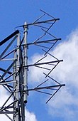
Four-bay crossed-dipole antenna of an FM broadcasting station
For example, an FMradio station which advertises that it has 100,000 watts of power actually has 100,000watts ERP, and not an actual 100,000-watt transmitter. The transmitter power output (TPO) of such a station typically may be 10,000–20,000watts, with a gain factor of 5–10× (5–10×, or 7–10dB). In most antenna designs, gain is realized primarily by concentrating power toward the horizontal plane and suppressing it at upward and downward angles, through the use of phased arrays of antenna elements. The distribution of power versus elevation angle is known as the vertical pattern. When an antenna is also directional horizontally, gain and ERP will vary with azimuth (compass direction). Rather than the average power over all directions, it is the apparent power in the direction of the peak of the antenna's main lobe that is quoted as a station's ERP (this statement is just another way of stating the definition of ERP). This is particularly applicable to the huge ERPs reported for shortwave broadcasting stations, which use very narrow beam widths to get their signals across continents and oceans.
United States regulatory usage
ERP for FM radio in the United States is always relative to a theoretical reference half-wave dipole antenna. (That is, when calculating ERP, the most direct approach is to work with antenna gain in dBd). To deal with antenna polarization, the Federal Communications Commission (FCC) lists ERP in both the horizontal and vertical measurements for FM and TV. Horizontal is the standard for both, but if the vertical ERP is larger it will be used instead.
The maximum ERP for US FM broadcasting is usually 100,000watts (FM ZoneII) or 50,000watts (in the generally more densely populated ZonesI and I-A), though exact restrictions vary depending on the class of license and the antenna height above average terrain (HAAT).[6] Some stations have been grandfathered in or, very infrequently, been given a waiver, and can exceed normal restrictions.
Microwave band issues
For most microwave systems, a completely non-directional isotropic antenna (one which radiates equally and perfectly well in every direction – a physical impossibility) is used as a reference antenna, and then one speaks of EIRP (effective isotropic radiated power) rather than ERP. This includes satellitetransponders, radar, and other systems which use microwave dishes and reflectors rather than dipole-style antennas.
Lower-frequency issues
In the case of medium wave (AM) stations in the United States, power limits are set to the actual transmitter power output, and ERP is not used in normal calculations. Omnidirectional antennas used by a number of stations radiate the signal equally in all horizontal directions. Directional arrays are used to protect co- or adjacent channel stations, usually at night, but some run directionally continuously. While antenna efficiency and ground conductivity are taken into account when designing such an array, the FCC database shows the station's transmitter power output, not ERP.
Related terms
According to the Institution of Electrical Engineers (UK), ERP is often used as a general reference term for radiated power, but strictly speaking should only be used when the antenna is a half-wave dipole,[7] and is used when referring to FM transmission.[8]
EMRP
Effective monopole radiated power (EMRP) may be used in Europe, particularly in relation to medium wave broadcasting antennas. This is the same as ERP, except that a short vertical antenna (i.e. a short monopole) is used as the reference antenna instead of a half-wave dipole.[7]
CMF
Cymomotive force (CMF) is an alternative term used for expressing radiation intensity in volts, particularly at the lower frequencies.[7] It is used in Australian legislation regulating AM broadcasting services, which describes it as: "for a transmitter, [it] means the product, expressed in volts, of:
(a) the electric field strength at a given point in space, due to the operation of the transmitter; and
(b) the distance of that point from the transmitter's antenna".[9]
It relates to AM broadcasting only, and expresses the field strength in "microvolts per metre at a distance of 1 kilometre from the transmitting antenna".[8]
The height above average terrain for VHF and higher frequencies is extremely important when considering ERP, as the signal coverage (broadcast range) produced by a given ERP dramatically increases with antenna height. Because of this, it is possible for a station of only a few hundred watts ERP to cover more area than a station of a few thousand watts ERP, if its signal travels above obstructions on the ground.
1 2 3 Barclay, Les, ed. (2003). Propagation of Radiowaves. Electromagnetics and Radar, IET Digital Library. Vol.2. Institution of Electrical Engineers (contributor). London: Institution of Engineering and Technology. pp.13–14. ISBN978-0-85296-102-5. Retrieved 14 September 2020.
This page is based on this Wikipedia article Text is available under the CC BY-SA 4.0 license; additional terms may apply. Images, videos and audio are available under their respective licenses.