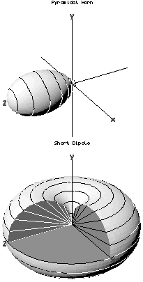
Three-dimensional antenna radiation patterns. The radial distance from the origin in any direction represents the strength of radiation emitted in that direction. The top shows the directive pattern of a horn antenna, the bottom shows the omnidirectional pattern of a simple vertical dipole antenna.
In the field of antenna design the term radiation pattern (or antenna pattern or far-field pattern) refers to the directional (angular) dependence of the strength of the radio waves from the antenna or other source.[1][2][3]
Particularly in the fields of fiber optics, lasers, and integrated optics, the term radiation pattern may also be used as a synonym for the near-field pattern or Fresnel pattern.[4] This refers to the positional dependence of the electromagnetic field in the near field, or Fresnel region of the source. The near-field pattern is most commonly defined over a plane placed in front of the source, or over a cylindrical or spherical surface enclosing it.[1][4]
The far-field pattern of an antenna may be determined experimentally at an antenna range, or alternatively, the near-field pattern may be found using a near-field scanner, and the radiation pattern deduced from it by computation.[1] The far-field radiation pattern can also be calculated from the antenna shape by computer programs such as NEC. Other software, like HFSS can also compute the near field.
The far field radiation pattern may be represented graphically as a plot of one of a number of related variables, like the field strength at a constant (large) radius (an amplitude pattern or field pattern), the power per unit solid angle (power pattern) and the directive gain. Very often, only the relative amplitude is plotted, normalized either to the amplitude on the antenna boresight, or to the total radiated power. The plotted quantity may be shown on a linear scale, or in dB. The plot is typically represented as a three-dimensional graph (as at right), or as separate graphs in the vertical plane and horizontal plane. This is often known as a polar diagram.
Reciprocity
The radiation patterns of a vertical half-wave dipole, an omnidirectional antenna. The horizontal and vertical polar patterns are projections of the 3 dimensional pattern onto horizontal and vertical planes, respectively. An omnidirectional antenna radiates equal signal strength in all horizontal directions, so its horizontal pattern is just a circle.
It is a fundamental property of antennas that the receiving pattern (sensitivity as a function of direction) of an antenna when used for receiving is identical to the far-field radiation pattern of the antenna when used for transmitting. This is a consequence of the reciprocity theorem of electromagnetics and is proved below. Therefore, in discussions of radiation patterns the antenna can be viewed as either transmitting or receiving, whichever is more convenient.
There are limits to reciprocity: It applies only to passive antenna elements – active antennas that incorporate amplifiers or other individually powered components are not reciprocal. And even when the antenna is made of exclusively of passive elements, reciprocity only applies to the waves emitted and intercepted by the antenna. Reciprocity does not apply to the distribution of current in the various parts of the antenna generated by the intercepted waves nor currents that create emitted waves: Antenna current profiles typically differ for receiving and transmitting, despite the waves in the far field radiating inward and outward along the same path, with the same overall pattern, just with reversed direction.
Typical patterns
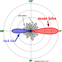
Typical polar radiation plot. Most antennas show a pattern of "lobes" or maxima of radiation. In a directive antenna, shown here, the largest lobe, in the desired direction of propagation, is called the "main lobe". The other lobes are called "sidelobes" and usually represent radiation in unwanted directions.
The simplest antennas, monopole and dipole antennas, consist of one or two straight metal rods along a common axis. These axially symmetric antennas have radiation patterns with a similar symmetry, called omnidirectional patterns; they radiate equal power in all directions perpendicular to the antenna, with the power varying only with the angle to the axis, dropping off to zero on the antenna's axis. This illustrates the general principle that if the shape of an antenna is symmetrical, its radiation pattern will have the same symmetry.
In most antennas, the radiation from the different parts of the antenna interferes at some angles; the radiation pattern of the antenna can be considered an interference pattern. This results in minimum or zero radiation at certain angles where the radio waves from the different parts arrive out of phase, and local maxima of radiation at other angles where the radio waves arrive in phase. Therefore, the radiation plot of most antennas shows a pattern of maxima called "lobes" at various angles, separated by "nulls" at which the radiation goes to zero. The larger the antenna is compared to a wavelength, the more lobes there will be.
A rectangular radiation plot, an alternative presentation method to a polar plot
In a directional antenna in which the objective is to emit the radio waves in one particular direction, the antenna is designed to radiate most of its power in the lobe directed in the desired direction. Therefore, in the radiation plot this lobe appears larger than the others; it is called the "main lobe". The axis of maximum radiation, passing through the center of the main lobe, is called the "beam axis" or boresight axis". In some antennas, such as split-beam antennas, there may exist more than one major lobe. The other lobes beside the main lobe, representing unwanted radiation in other directions, are called minor lobes. The minor lobes oriented at an angle to the main lobe are called "side lobes". The minor lobe in the opposite direction (180°) from the main lobe is called the "back lobe".
Minor lobes usually represent radiation in undesired directions, so in directional antennas a design goal is usually to reduce the minor lobes. Side lobes are normally the largest of the minor lobes. The level of minor lobes is usually expressed as a ratio of the power density in the lobe in question to that of the major lobe. This ratio is often termed the side lobe ratio or side lobe level. Side lobe levels of −20dB or greater are usually not desirable in many applications. Attainment of a side lobe level smaller than −30dB usually requires very careful design and construction. In most radar systems, for example, low side lobe ratios are very important to minimize false target indications through the side lobes.
For a complete proof, see the reciprocity (electromagnetism) article. Here, we present a common simple proof limited to the approximation of two antennas separated by a large distance compared to the size of the antenna, in a homogeneous medium. The first antenna is the test antenna whose patterns are to be investigated; this antenna is free to point in any direction. The second antenna is a reference antenna, which points rigidly at the first antenna.
Each antenna is alternately connected to a transmitter having a particular source impedance, and a receiver having the same input impedance (the impedance may differ between the two antennas).
It is assumed that the two antennas are sufficiently far apart that the properties of the transmitting antenna are not affected by the load placed upon it by the receiving antenna. Consequently, the amount of power transferred from the transmitter to the receiver can be expressed as the product of two independent factors; one depending on the directional properties of the transmitting antenna, and the other depending on the directional properties of the receiving antenna.
For the transmitting antenna, by the definition of gain, , the radiation power density at a distance from the antenna (i.e. the power passing through unit area) is
.
Here, the angles and indicate a dependence on direction from the antenna, and stands for the power the transmitter would deliver into a matched load. The gain may be broken down into three factors; the antenna gain (the directional redistribution of the power), the radiation efficiency (accounting for ohmic losses in the antenna), and lastly the loss due to mismatch between the antenna and transmitter. Strictly, to include the mismatch, it should be called the realized gain,[4] but this is not common usage.
For the receiving antenna, the power delivered to the receiver is
.
Here is the power density of the incident radiation, and is the antenna aperture or effective area of the antenna (the area the antenna would need to occupy in order to intercept the observed captured power). The directional arguments are now relative to the receiving antenna, and again is taken to include ohmic and mismatch losses.
Putting these expressions together, the power transferred from transmitter to receiver is
,
where and are directionally dependent properties of the transmitting and receiving antennas respectively. For transmission from the reference antenna (2), to the test antenna (1), that is
,
and for transmission in the opposite direction
.
Here, the gain and effective area of antenna 2 are fixed, because the orientation of this antenna is fixed with respect to the first.
Now for a given disposition of the antennas, the reciprocity theorem requires that the power transfer is equally effective in each direction, i.e.
,
whence
.
But the right hand side of this equation is fixed (because the orientation of antenna 2 is fixed), and so
,
i.e. the directional dependence of the (receiving) effective aperture and the (transmitting) gain are identical (QED). Furthermore, the constant of proportionality is the same irrespective of the nature of the antenna, and so must be the same for all antennas. Analysis of a particular antenna (such as a Hertzian dipole), shows that this constant is , where is the free-space wavelength. Hence, for any antenna the gain and the effective aperture are related by
.
Even for a receiving antenna, it is more usual to state the gain than to specify the effective aperture. The power delivered to the receiver is therefore more usually written as
(see link budget). The effective aperture is however of interest for comparison with the actual physical size of the antenna.
Practical consequences
When determining the pattern of a receiving antenna by computer simulation, it is not necessary to perform a calculation for every possible angle of incidence. Instead, the radiation pattern of the antenna is determined by a single simulation, and the receiving pattern inferred by reciprocity.
When determining the pattern of an antenna by measurement, the antenna may be either receiving or transmitting, whichever is more convenient.
For a practical antenna, the side lobe level should be minimum, it is necessary to have the maximum directivity.[5]
In physics, the cross section is a measure of the probability that a specific process will take place in a collision of two particles. For example, the Rutherford cross-section is a measure of probability that an alpha particle will be deflected by a given angle during an interaction with an atomic nucleus. Cross section is typically denoted σ (sigma) and is expressed in units of area, more specifically in barns. In a way, it can be thought of as the size of the object that the excitation must hit in order for the process to occur, but more exactly, it is a parameter of a stochastic process.
Diffraction is the interference or bending of waves around the corners of an obstacle or through an aperture into the region of geometrical shadow of the obstacle/aperture. The diffracting object or aperture effectively becomes a secondary source of the propagating wave. Italian scientist Francesco Maria Grimaldi coined the word diffraction and was the first to record accurate observations of the phenomenon in 1660.
In electromagnetics, an antenna's gain is a key performance parameter which combines the antenna's directivity and radiation efficiency. The term power gain has been deprecated by IEEE. In a transmitting antenna, the gain describes how well the antenna converts input power into radio waves headed in a specified direction. In a receiving antenna, the gain describes how well the antenna converts radio waves arriving from a specified direction into electrical power. When no direction is specified, gain is understood to refer to the peak value of the gain, the gain in the direction of the antenna's main lobe. A plot of the gain as a function of direction is called the antenna pattern or radiation pattern. It is not to be confused with directivity, which does not take an antenna's radiation efficiency into account.
A parabolic antenna is an antenna that uses a parabolic reflector, a curved surface with the cross-sectional shape of a parabola, to direct the radio waves. The most common form is shaped like a dish and is popularly called a dish antenna or parabolic dish. The main advantage of a parabolic antenna is that it has high directivity. It functions similarly to a searchlight or flashlight reflector to direct radio waves in a narrow beam, or receive radio waves from one particular direction only. Parabolic antennas have some of the highest gains, meaning that they can produce the narrowest beamwidths, of any antenna type. In order to achieve narrow beamwidths, the parabolic reflector must be much larger than the wavelength of the radio waves used, so parabolic antennas are used in the high frequency part of the radio spectrum, at UHF and microwave (SHF) frequencies, at which the wavelengths are small enough that conveniently sized reflectors can be used.
In radio and telecommunications a dipole antenna or doublet is one of the two simplest and most widely-used types of antenna; the other is the monopole. The dipole is any one of a class of antennas producing a radiation pattern approximating that of an elementary electric dipole with a radiating structure supporting a line current so energized that the current has only one node at each far end. A dipole antenna commonly consists of two identical conductive elements such as metal wires or rods. The driving current from the transmitter is applied, or for receiving antennas the output signal to the receiver is taken, between the two halves of the antenna. Each side of the feedline to the transmitter or receiver is connected to one of the conductors. This contrasts with a monopole antenna, which consists of a single rod or conductor with one side of the feedline connected to it, and the other side connected to some type of ground. A common example of a dipole is the "rabbit ears" television antenna found on broadcast television sets. All dipoles are electrically equivalent to two monopoles mounted end-to-end and fed with opposite phases, with the ground plane between them made "virtual" by the opposing monopole.
In telecommunications, particularly in radio frequency engineering, signal strength refers to the transmitter power output as received by a reference antenna at a distance from the transmitting antenna. High-powered transmissions, such as those used in broadcasting, are expressed in dB-millivolts per metre (dBmV/m). For very low-power systems, such as mobile phones, signal strength is usually expressed in dB-microvolts per metre (dBμV/m) or in decibels above a reference level of one milliwatt (dBm). In broadcasting terminology, 1 mV/m is 1000 μV/m or 60 dBμ.
In electromagnetics and antenna theory, the aperture of an antenna is defined as "A surface, near or on an antenna, on which it is convenient to make assumptions regarding the field values for the purpose of computing fields at external points. The aperture is often taken as that portion of a plane surface near the antenna, perpendicular to the direction of maximum radiation, through which the major part of the radiation passes."
In probability and statistics, a circular distribution or polar distribution is a probability distribution of a random variable whose values are angles, usually taken to be in the range [0, 2π). A circular distribution is often a continuous probability distribution, and hence has a probability density, but such distributions can also be discrete, in which case they are called circular lattice distributions. Circular distributions can be used even when the variables concerned are not explicitly angles: the main consideration is that there is not usually any real distinction between events occurring at the opposite ends of the range, and the division of the range could notionally be made at any point.
Etendue or étendue is a property of light in an optical system, which characterizes how "spread out" the light is in area and angle. It corresponds to the beam parameter product (BPP) in Gaussian beam optics. Other names for etendue include acceptance, throughput, light grasp, light-gathering power, optical extent, and the AΩ product. Throughput and AΩ product are especially used in radiometry and radiative transfer where it is related to the view factor. It is a central concept in nonimaging optics.
In probability theory and directional statistics, the von Mises distribution is a continuous probability distribution on the circle. It is a close approximation to the wrapped normal distribution, which is the circular analogue of the normal distribution. A freely diffusing angle on a circle is a wrapped normally distributed random variable with an unwrapped variance that grows linearly in time. On the other hand, the von Mises distribution is the stationary distribution of a drift and diffusion process on the circle in a harmonic potential, i.e. with a preferred orientation. The von Mises distribution is the maximum entropy distribution for circular data when the real and imaginary parts of the first circular moment are specified. The von Mises distribution is a special case of the von Mises–Fisher distribution on the N-dimensional sphere.
An isotropic radiator is a theoretical point source of waves which radiates the same intensity of radiation in all directions. It may be based on sound waves or electromagnetic waves, in which case it is also known as an isotropic antenna. It has no preferred direction of radiation, i.e., it radiates uniformly in all directions over a sphere centred on the source.
Antenna measurement techniques refers to the testing of antennas to ensure that the antenna meets specifications or simply to characterize it. Typical parameters of antennas are gain, bandwidth, radiation pattern, beamwidth, polarization, and impedance.
In electromagnetics, directivity is a parameter of an antenna or optical system which measures the degree to which the radiation emitted is concentrated in a single direction. It is the ratio of the radiation intensity in a given direction from the antenna to the radiation intensity averaged over all directions. Therefore, the directivity of a hypothetical isotropic radiator is 1, or 0 dBi.
There are several equivalent ways for defining trigonometric functions, and the proofs of the trigonometric identities between them depend on the chosen definition. The oldest and most elementary definitions are based on the geometry of right triangles and the ratio between their sides. The proofs given in this article use these definitions, and thus apply to non-negative angles not greater than a right angle. For greater and negative angles, see Trigonometric functions.
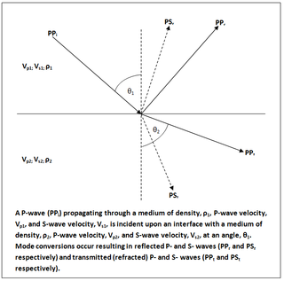
In geophysics and reflection seismology, the Zoeppritz equations are a set of equations that describe the partitioning of seismic wave energy at an interface, due to mode conversion. They are named after their author, the German geophysicist Karl Bernhard Zoeppritz, who died before they were published in 1919.
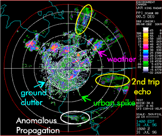
Clutter is the unwanted return (echoes) in electronic systems, particularly in reference to radars. Such echoes are typically returned from ground, sea, rain, animals/insects, chaff and atmospheric turbulences, and can cause serious performance issues with radar systems. What one person considers to be unwanted clutter, another may consider to be a wanted target. However, targets usually refer to point scatterers and clutter to extended scatterers. The clutter may fill a volume or be confined to a surface. A knowledge of the volume or surface area illuminated is required to estimated the echo per unit volume, η, or echo per unit surface area, σ°.
Antenna gain-to-noise-temperature (G/T) is a figure of merit in the characterization of antenna performance, where G is the antenna gain in decibels at the receive frequency, and T is the equivalent noise temperature of the receiving system in kelvins. The receiving system noise temperature is the summation of the antenna noise temperature and the RF chain noise temperature from the antenna terminals to the receiver output.
Photon transport in biological tissue can be equivalently modeled numerically with Monte Carlo simulations or analytically by the radiative transfer equation (RTE). However, the RTE is difficult to solve without introducing approximations. A common approximation summarized here is the diffusion approximation. Overall, solutions to the diffusion equation for photon transport are more computationally efficient, but less accurate than Monte Carlo simulations.
In probability theory and directional statistics, a wrapped exponential distribution is a wrapped probability distribution that results from the "wrapping" of the exponential distribution around the unit circle.
The two-rays ground-reflection model is a multipath radio propagation model which predicts the path losses between a transmitting antenna and a receiving antenna when they are in line of sight (LOS). Generally, the two antenna each have different height. The received signal having two components, the LOS component and the reflection component formed predominantly by a single ground reflected wave.
References
1 2 3 Constantine A. Balanis: “Antenna Theory, Analysis and Design”, John Wiley & Sons, Inc., 2nd ed. 1982 ISBN0-471-59268-4
↑ David K Cheng: “Field and Wave Electromagnetics”, Addison-Wesley Publishing Company Inc., Edition 2, 1998. ISBN0-201-52820-7
↑ Edward C. Jordan & Keith G. Balmain; “Electromagnetic Waves and Radiating Systems” (2nd ed. 1968) Prentice-Hall. ISBN81-203-0054-8
1 2 3 Institute of Electrical and Electronics Engineers, “The IEEE standard dictionary of electrical and electronics terms”; 6th ed. New York, N.Y., Institute of Electrical and Electronics Engineers, c1997. IEEE Std 100-1996. ISBN1-55937-833-6 [ed. Standards Coordinating Committee 10, Terms and Definitions; Jane Radatz, (chair)]
↑ Singh, Urvinder; Salgotra, Rohit (20 July 2016). "Synthesis of linear antenna array using flower pollination algorithm". Neural Computing and Applications. 29 (2): 435–445. doi:10.1007/s00521-016-2457-7. S2CID22745168.
This page is based on this Wikipedia article Text is available under the CC BY-SA 4.0 license; additional terms may apply. Images, videos and audio are available under their respective licenses.