Beam tilt

Last updated

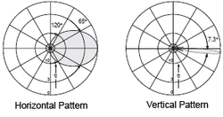
Beam tilt is used in radio to aim the main lobe of the vertical plane radiation pattern of an antenna below (or above) the horizontal plane.

The simplest way is mechanical beam tilt, where the antenna is physically mounted in such a manner as to lower the angle of the signal on one side. However, this also raises it on the other side, making it useful in only very limited situations.

Horizontal and vertical radiation patterns, the latter with a pronounced downward beam tilt Sector antenna radiation pattern.png
Horizontal and vertical radiation patterns, the latter with a pronounced downward beam tilt

More common is electrical beam tilt, where the phasing between antenna elements is tweaked to make the signal go down (usually) in all directions. [1] This is extremely useful when the antenna is at a very high point, and the edge of the signal is likely to miss the target (broadcast audience, cellphone users, etc.) entirely.

With electrical tilting, front and back lobes tilt in the same direction. For example, an electrical downtilt will make both the front lobe and the back lobe tilt down. This is the property used in the above example where the signal is pointed down in all directions. On the contrary, mechanical downtilting will make the front lobe tilt down and the back lobe tilt up. In almost all practical cases, antennas are only tilted down – though tilting up is technically possible.

The use of purely electrical tilt with no mechanical tilt is an attractive choice for aesthetic reasons which are very important for operators seeking acceptance of integrated antennas in visible locations.

In GSM and UMTS cellular networks, mechanical tilt is almost always fixed whereas electrical tilt can be controlled using remote actuators and position sensors, thus reducing operating expenses. Remote electrical tilt is abbreviated as RET and it is part of the Antenna Interface Standards Group's open specification for the control interface of antenna devices. [2]

Occasionally, mechanical and electrical tilt will be used together in order to create greater beam tilt in one direction than the other, mainly to accommodate unusual terrain. Along with null fill, beam tilt is the essential parameter controlling the focus of radio communications, and together they can create almost infinite combinations of 3-D radiation patterns for any situation.

Beam tilt optimization

Beam tilt optimization is a network optimization technique used in mobile networks aiming at controlling the inclination of the vertical tilt angle of the antenna in order to optimize a set of network performance indicators.

Different studies in beam tilt optimization [3] focus on Coverage-Capacity Optimization (CCO), for which the goal is to control the beam tilt in order to jointly optimize the radio coverage and capacity in the network cells and reduce interference from neighbouring cells.

There exists mainly two types of approaches to beam tilt optimization:

  1. Rule-based algorithms: consist of optimization strategies based on domain knowledge and control theory, and mainly based on the optimization of utility metrics, [4] or threshold-based policies employing Fuzzy Logic (FL) to model representative network performance indicators. [5]
  2. Data-driven algorithms : consist of optimization strategies based on the use learning techniques based on the availability of network data (e.g. Contextual Bandit (CB) techniques), or by directly interacting with the environment (e.g. Reinforcement Learning (RL) techniques [3] [6] )

Related Research Articles

Beam steering is a technique for changing the direction of the main lobe of a radiation pattern.

<span class="mw-page-title-main">Reflective array antenna</span>

In telecommunications and radar, a reflective array antenna is a class of directive antennas in which multiple driven elements are mounted in front of a flat surface designed to reflect the radio waves in a desired direction. They are a type of array antenna. They are often used in the VHF and UHF frequency bands. VHF examples are generally large and resemble a highway billboard, so they are sometimes called billboard antennas. Other names are bedspring array and bowtie array depending on the type of elements making up the antenna. The curtain array is a larger version used by shortwave radio broadcasting stations.

<span class="mw-page-title-main">Wireless</span> Transfer of information or power that does not require the use of physical wires

Wireless communication is the transfer of information (telecommunication) between two or more points without the use of an electrical conductor, optical fiber or other continuous guided medium for the transfer. The most common wireless technologies use radio waves. With radio waves, intended distances can be short, such as a few meters for Bluetooth or as far as millions of kilometers for deep-space radio communications. It encompasses various types of fixed, mobile, and portable applications, including two-way radios, cellular telephones, personal digital assistants (PDAs), and wireless networking. Other examples of applications of radio wireless technology include GPS units, garage door openers, wireless computer mouse, keyboards and headsets, headphones, radio receivers, satellite television, broadcast television and cordless telephones. Somewhat less common methods of achieving wireless communications involve other electromagnetic phenomena, such as light and magnetic or electric fields, or the use of sound.

<span class="mw-page-title-main">Helical antenna</span> Type of antenna

A helical antenna is an antenna consisting of one or more conducting wires wound in the form of a helix. A helical antenna made of one helical wire, the most common type, is called monofilar, while antennas with two or four wires in a helix are called bifilar, or quadrifilar, respectively.

<span class="mw-page-title-main">Wireless power transfer</span> Transmission of electrical energy without wires as a physical link

Wireless power transfer (WPT), wireless power transmission, wireless energy transmission (WET), or electromagnetic power transfer is the transmission of electrical energy without wires as a physical link. In a wireless power transmission system, a transmitter device, driven by electric power from a power source, generates a time-varying electromagnetic field, which transmits power across space to a receiver device, which extracts power from the field and supplies it to an electrical load. The technology of wireless power transmission can eliminate the use of the wires and batteries, thus increasing the mobility, convenience, and safety of an electronic device for all users. Wireless power transfer is useful to power electrical devices where interconnecting wires are inconvenient, hazardous, or are not possible.

<span class="mw-page-title-main">Cell site</span> Communications equipment location

A cell site, cell phone tower, cell base tower, or cellular base station is a cellular-enabled mobile device site where antennas and electronic communications equipment are placed to create a cell, or adjacent cells, in a cellular network. The raised structure typically supports antenna and one or more sets of transmitter/receivers transceivers, digital signal processors, control electronics, a GPS receiver for timing, primary and backup electrical power sources, and sheltering.

A cognitive radio (CR) is a radio that can be programmed and configured dynamically to use the best wireless channels in its vicinity to avoid user interference and congestion. Such a radio automatically detects available channels in wireless spectrum, then accordingly changes its transmission or reception parameters to allow more concurrent wireless communications in a given spectrum band at one location. This process is a form of dynamic spectrum management.

Beamforming or spatial filtering is a signal processing technique used in sensor arrays for directional signal transmission or reception. This is achieved by combining elements in an antenna array in such a way that signals at particular angles experience constructive interference while others experience destructive interference. Beamforming can be used at both the transmitting and receiving ends in order to achieve spatial selectivity. The improvement compared with omnidirectional reception/transmission is known as the directivity of the array.

<span class="mw-page-title-main">Conical scanning</span> System used in radar to improve accuracy

Conical scanning is a system used in early radar units to improve their accuracy, as well as making it easier to steer the antenna properly to point at a target. Conical scanning is similar in concept to the earlier lobe switching concept used on some of the earliest radars, and many examples of lobe switching sets were modified in the field to conical scanning during World War II, notably the German Würzburg radar. Antenna guidance can be made entirely automatic, as in the American SCR-584. Potential failure modes and susceptibility to deception jamming led to the replacement of conical scan systems with monopulse radar sets. They are still used by the Deep Space Network for maintaining communications links to space probes. The spin-stabilized Pioneer 10 and Pioneer 11 probes used onboard conical scanning maneuvers to track Earth in its orbit.

A sector antenna is a type of directional microwave antenna with a sector-shaped radiation pattern. The word "sector" is used in the geometric sense; some portion of the circumference of a circle measured in degrees of arc. 60°, 90° and 120° designs are typical, often with a few degrees 'extra' to ensure overlap and mounted in multiples when wider or full-circle coverage is required. The largest use of these antennas is as antennas for cell phone base-station sites. They are also used for other types of mobile communications, for example in Wi-Fi networks. They are used for limited-range distances of around 4 to 5 km.

Multi-user MIMO (MU-MIMO) is a set of multiple-input and multiple-output (MIMO) technologies for multipath wireless communication, in which multiple users or terminals, each radioing over one or more antennas, communicate with one another. In contrast, single-user MIMO (SU-MIMO) involves a single multi-antenna-equipped user or terminal communicating with precisely one other similarly equipped node. Analogous to how OFDMA adds multiple-access capability to OFDM in the cellular-communications realm, MU-MIMO adds multiple-user capability to MIMO in the wireless realm.

In radio, cooperative multiple-input multiple-output is a technology that can effectively exploit the spatial domain of mobile fading channels to bring significant performance improvements to wireless communication systems. It is also called network MIMO, distributed MIMO, virtual MIMO, and virtual antenna arrays.

<span class="mw-page-title-main">MIMO</span> Use of multiple antennas in radio

In radio, multiple-input and multiple-output (MIMO) is a method for multiplying the capacity of a radio link using multiple transmission and receiving antennas to exploit multipath propagation. MIMO has become an essential element of wireless communication standards including IEEE 802.11n, IEEE 802.11ac, HSPA+ (3G), WiMAX, and Long Term Evolution (LTE). More recently, MIMO has been applied to power-line communication for three-wire installations as part of the ITU G.hn standard and of the HomePlug AV2 specification.

Many antennas is a smart antenna technique which overcomes the performance limitation of single user multiple-input multiple-output (MIMO) techniques. In cellular communication, the maximum number of considered antennas for downlink is 2 and 4 to support 3GPP Long Term Evolution (LTE) and IMT Advanced requirements, respectively. Since the available spectrum band will probably be limited while the data rate requirement will continuously increase beyond IMT-A to support the mobile multimedia services, it is highly probable that the number of transmit antennas at the base station must be increased to 8–64 or more. The installation of many antennas at single base stations introduced many challenges and required development of several high technologies: a new SDMA engine, a new beamforming algorithm and a new antenna array.

<span class="mw-page-title-main">Antenna array</span>

An antenna array is a set of multiple connected antennas which work together as a single antenna, to transmit or receive radio waves. The individual antennas are usually connected to a single receiver or transmitter by feedlines that feed the power to the elements in a specific phase relationship. The radio waves radiated by each individual antenna combine and superpose, adding together to enhance the power radiated in desired directions, and cancelling to reduce the power radiated in other directions. Similarly, when used for receiving, the separate radio frequency currents from the individual antennas combine in the receiver with the correct phase relationship to enhance signals received from the desired directions and cancel signals from undesired directions. More sophisticated array antennas may have multiple transmitter or receiver modules, each connected to a separate antenna element or group of elements.

The first smart antennas were developed for military communications and intelligence gathering. The growth of cellular telephone in the 1980s attracted interest in commercial applications. The upgrade to digital radio technology in the mobile phone, indoor wireless network, and satellite broadcasting industries created new opportunities for smart antennas in the 1990s, culminating in the development of the MIMO technology used in 4G wireless networks.

Bernhard H. Walke is a pioneer of mobile Internet access and professor emeritus at RWTH Aachen University in Germany. He is a driver of wireless and mobile 2G to 5G cellular radio networks technologies. In 1985, he proposed a local cellular radio network comprising technologies in use today in 2G, 4G and discussed for 5G systems. For example, self-organization of a radio mesh network, integration of circuit- and packet switching, de-centralized radio resource control, TDMA/spread spectrum data transmission, antenna beam steering, spatial beam multiplexing, interference coordination, S-Aloha based multiple access and demand assigned traffic channels, mobile broadband transmission using mm-waves, and multi-hop communication.

<span class="mw-page-title-main">Reconfigurable antenna</span> Antenna capable of modifying its frequency and radiation properties dynamically

A reconfigurable antenna is an antenna capable of modifying its frequency and radiation properties dynamically, in a controlled and reversible manner. In order to provide a dynamic response, reconfigurable antennas integrate an inner mechanism that enable the intentional redistribution of the RF currents over the antenna surface and produce reversible modifications of its properties. Reconfigurable antennas differ from smart antennas because the reconfiguration mechanism lies inside the antenna, rather than in an external beamforming network. The reconfiguration capability of reconfigurable antennas is used to maximize the antenna performance in a changing scenario or to satisfy changing operating requirements.

Three-dimensional beamforming (3DBF), full dimension MIMO or tilt angle adaptation is an interference coordination method in cellular networks and radar systems which brings significant improvements in comparison with conventional 2D beamforming techniques. Most beamforming schemes currently employed in wireless cellular networks control the beam pattern radiation in the horizontal plane. In contrast to such two-dimensional beamforming (2DBF), 3DBF adapts the radiation beam pattern in both elevation and azimuth planes to provide more degrees of freedom in supporting users. By utilizing information on angle of arrival (AoA) of users provided by suitable antenna hardware such as sector antenna or planar array in both elevation and azimuth planes and estimating direction of arrival (DoA) of each users' signal, base station is capable of distinguishing different users using proper beamforming and also steering the array's beam to a desired direction which optimizes some preferred performance metric of the network.

Chan-Byoung Chae is a Korean computer scientist, electrical engineer, and academic. He is an Underwood Distinguished Professor, the director of Intelligence Networking Laboratory, and head of the School of Integrated Technology at Yonsei University, Korea.

References

  1. Alexander, W.C. (6 November 2002). "Overshoots and Close-In Coverage". Radio World. Archived from the original on 3 August 2010. Retrieved 2009-08-14.{{cite news}}: CS1 maint: unfit URL (link)
  2. "Archived copy" (PDF). www.torni.fi. Archived from the original (PDF) on 20 July 2011. Retrieved 12 January 2022.{{cite web}}: CS1 maint: archived copy as title (link)
  3. 1 2 Dandanov, Nikolay; Al-Shatri, Hussein; Klein, Anja; Poulkov, Vladimir (2016-10-27). "Dynamic Self-Optimization of the Antenna Tilt for Best Trade-off Between Coverage and Capacity in Mobile Networks". Wireless Personal Communications. 92 (1): 251–278. doi:10.1007/s11277-016-3849-9. ISSN   0929-6212. S2CID   37595264.
  4. Eckhardt, Harald; Klein, Siegfried; Gruber, Markus (May 2011). "Vertical Antenna Tilt Optimization for LTE Base Stations". 2011 IEEE 73rd Vehicular Technology Conference (VTC Spring). IEEE. pp. 1–5. doi:10.1109/vetecs.2011.5956370. ISBN   978-1-4244-8332-7. S2CID   9179981.
  5. Saeed, Arsalan; Aliu, Osianoh Glenn; Imran, Muhammad Ali (April 2012). "Controlling self healing cellular networks using fuzzy logic". 2012 IEEE Wireless Communications and Networking Conference (WCNC). IEEE. pp. 3080–3084. doi:10.1109/wcnc.2012.6214334. ISBN   978-1-4673-0437-5. S2CID   12043190.
  6. Balevi, Eren; Andrews, Jeffrey G. (December 2019). "Online Antenna Tuning in Heterogeneous Cellular Networks With Deep Reinforcement Learning". IEEE Transactions on Cognitive Communications and Networking. 5 (4): 1113–1124. arXiv: 1903.06787 . doi:10.1109/tccn.2019.2933420. ISSN   2332-7731. S2CID   81979656.