A diplexer is a passive device that implements frequency-domain multiplexing. Two ports (e.g., L and H) are multiplexed onto a third port (e.g., S). The signals on ports L and H occupy disjoint frequency bands. Consequently, the signals on L and H can coexist on port S without interfering with each other.
Typically, the signal on port L will occupy a single low frequency band and the signal on port H will occupy a higher frequency band. In that situation, the diplexer consists of a lowpass filter connecting ports L and S and high pass filter connecting ports H and S. Ideally, all the lowband signal power on port L is transferred to the S port and vice versa. All the highband signal power on port H is transferred to port S and vice versa. Ideally, the separation of the signals is complete. None of the low band signal is transferred from the L port to the H port. In the real world, some power will be lost, and some signal power will leak to the wrong port.
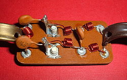
Television diplexer consisting of a high-pass filter (left) and a low-pass filter (right). The antenna cable is connected on the back to the screw terminals to the left of center.
The diplexer, being a passive device, is normally reciprocal: the device itself doesn't have a notion of input or output. However poorly designed diplexers may have differing impedance on various ports, so it should not simply be assumed that any such device is fully reciprocal unless it is stated or the return loss measured.
The diplexer is a different device than a passive combiner or splitter. The ports of a diplexer are frequency selective; the ports of a combiner are not. There is also a power "loss" difference - a combiner takes all the power delivered to the S port and equally divides it between the A and B ports. A diplexer does not.
A diplexer frequency multiplexes two ports onto one port, but more than two ports may be multiplexed. A three-port to one-port multiplexer is known as a triplexer, and a four-port to one-port multiplexer is a quadplexer or quadruplexer.
A typical diplexer may have around 30dB isolation between its L and H ports. That isolation is sufficient for many applications, but it is insufficient to allow simultaneous reception and transmission on one antenna. If the transmitter emits 1kW, then 1W of that signal would appear at the receiver; that 1W may be enough power to overload the receiver. Diplexers designed for simultaneous reception and transmission have more stringent isolation requirements and are known as duplexers.
Common uses
A diplexer allows two different devices to share a common communications channel. Typically, the channel is a long coaxial cable, and a diplexer is often used at both ends of the coaxial cable. The plan is feasible if the two devices operate on different frequencies. The plan is economical if the diplexers cost less than running a second cable.
Diplexers are typically used with radio receivers or transmitters on different, widely separated, frequency bands. A single city radio tower might have a police department antenna on 460MHz and a fire department antenna on 156MHz. A diplexer at the top combines the two antenna signals to the single coaxial feedline, and a second identical diplexer inside the building separates the feedline signals to the two dispatch radios. Some diplexers support as many as four antennas or radios that work on different radio bands.
Diplexers are also commonly used where a multi-band antenna is used on a tower, with a common feedline. The diplexer will split the two bands inside the building (such as VHF and UHF systems combined with a diplexer onto a common antenna).
Industrial applications
Diplexing is used to prevent intermodulation and keep reflected power (VSWR) to a minimum for each input transmitter and frequency. While diplexers can combine a relatively wide bandwidth, the major limitation comes with the antenna itself, which must be sufficiently wideband to accept all of the signals being passed through it, and transfer them to the airefficiently.
Typically with a multi-band antenna the frequencies in use will bear an odd harmonic relationship to each other to take advantage of natural harmonic resonances (such as 145/435MHz), making a highly efficient multi-band antenna. Other times tuned traps will be used, which is less efficient and generally not a technique used at VHF/UHF.
Many other large UHF-/VHF-transmitters use diplexers. The number of transmitters which can share an antenna is restricted by the spacing of their frequency bands. Transmitters whose frequencies are too close together cannot be combined successfully by a diplexer.
Diplexers are also used at medium wave broadcasting stations. However their use is not that common in this frequency range because the corresponding wavelength varies much more across the medium wave band than across the FM band and so it is more practicable to use a separate antenna for each frequency: medium wave transmission sites usually broadcast only on one to four frequencies, while FM-broadcasting sites often uses four and more frequencies.
Diplexers may be used as a back-up device. An example is maintenance work at one antenna of a medium wave transmission site that has two antennas transmitting on two frequencies. Then the other antenna can be used for broadcasting both channels. If it is not possible to build a second antenna for the second transmitter due to space constraints, then the diplexer is used permanently.
At long wave broadcasting sites diplexers are normally not used since these stations usually broadcast on only one frequency. A realization of diplexers for long wave broadcasting stations may be difficult, as the ratio of bandwidth (9kHz) to transmission frequency is high.
Diplexers are not used at VLF transmitters. In this frequency range their realization is very difficult because of the very high voltages that occur in the huge tuned loading coils that are used in the antenna feed.
Diplexers are also used in the home to allow a direct broadcastsatellite TVdish antenna and a terrestrial TV antenna (local broadcast channels) to share one coaxial cable. The dish antenna occupies the high frequencies (typically 950 to 1450MHz), and the TV antenna uses lower television channel frequencies (typically 50 to 870MHz). In addition, the satellite also gets a DC to low frequency band to power the dish's block converter and select the dish antenna polarization (e.g., voltage signaling or DiSEqC). The diplexer is useful in homes that are already wired with one cable, because it eliminates the need to install a second cable. For the diplexer to work, the existing cable must be able to pass the satellite frequencies with little loss. Older TV installations may use a solid dielectric RG-59 cable, and that cable may be inadequate.[1]RG-6 cable is typically used for satellite feed lines.
In this application, there would be a diplexer on the roof that joins the satellite dish feed and the TV antenna together into a single coaxial cable. That cable would then run from the roof into the house. At a convenient point, a second diplexer would split the two signals apart; one signal would go to the TV set and the other to the IRD of the DBS set-top box. These usually have an antenna input and a diplexer, so that the antenna signal is also distributed along with the satellite.
More modern installations confront several issues. There are often multiple satellite dishes that need to feed several receivers or even multichannel receivers. See, for example, single cable distribution.
Diplexers were also used to combine UHF TV and VHF TV and FM signals onto one downlead, which can then be split back into its component parts as required.
↑ Legacy satellite receivers instructed the LNB to send only one polarization (half the possible channels). Modern receivers have dual channels, so they may need both polarizations at the same time. A DishPro LNB "stacks" the two polarizations (sends both polarizations down the same cable; one polarization is sent in a higher (stacked) band). Consequently, the LNB signal occupies a wider bandwidth, 950 to 2150MHz. RG-59 has significant loss at the higher frequencies.
This page is based on this Wikipedia article Text is available under the CC BY-SA 4.0 license; additional terms may apply. Images, videos and audio are available under their respective licenses.