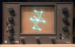
A video vectorscope displaying color bars. The diagonal direction of the colorburst vector is indicative of a NTSC signal.The graticule of an NTSC vectorscope. A PAL vectorscope displaying color bars.
A vectorscope is a special type of oscilloscope used in both audio and video applications.[1] Whereas an oscilloscope or waveform monitor normally displays a plot of signal vs. time, a vectorscope displays an X-Y plot of two signals, which can reveal details about the relationship between these two signals. Vectorscopes are highly similar in operation to oscilloscopes operated in X-Y mode; however those used in video applications have specialized graticules, and accept standard television or video signals as input (demodulating and demultiplexing the two components to be analyzed internally).
This section is missing information about more details on digital use, e.g. color matching, preferably with example output of real-life images. Please expand the section to include this information. Further details may exist on the talk page.(July 2021)
In video applications, a vectorscope supplements a waveform monitor for the purpose of measuring and testing television signals, regardless of format (NTSC, PAL, SECAM or any number of digital television standards). While a waveform monitor allows a broadcast technician to measure the overall characteristics of a video signal, a vectorscope is used to visualize chrominance, which is encoded into the video signal as a subcarrier of specific frequencies.[2] The vectorscope locks exclusively to the chrominance subcarrier in the video signal (at 3.58MHz for NTSC or 4.43MHz for PAL) to drive its display. In digital applications, a vectorscope instead plots the Cb and Cr channels against each other (these are the two channels in digital formats which contain chroma information).
A vectorscope uses an overlaid circular reference display, or graticule, for visualizing chrominance signals, which is the best method of referring to the QAM scheme used to encode color into a video signal. The actual visual pattern that the incoming chrominance signal draws on the vectorscope is called the trace. Chrominance is measured using two methods—color saturation, encoded as the amplitude, or gain, of the subcarrier signal, and hue, encoded as the subcarrier's phase. The vectorscope's graticule roughly represents saturation as distance from the center of the circle, and hue as the angle, in standard position, around it. The graticule is also embellished with several elements corresponding to the various components of the standard color bars video test signal, including boxes around the circles for the colors in the main bars, and perpendicular lines corresponding to the U and V components of the chrominance signal (and additionally on an NTSC vectorscope, the I and Q components). NTSC vectorscopes have one set of boxes for the color bars, while their PAL counterparts have two sets of boxes, because the R-Y chrominance component in PAL reverses in phase on alternating lines. Another element in the graticule is a fine grid at 270° on the display (i.e. the -U position) used for measuring differential gain and phase.
Often two sets of bar targets are provided: one for color bars at 75% amplitude and one for color bars at 100% amplitude. The 100% bars represent the maximum amplitude (of the composite signal) that composite encoding allows for. 100% bars are not suitable for broadcast and are not broadcast-safe. 75% bars have reduced amplitude and are broadcast-safe.
Some vectorscope models have only one set of bar targets. The vectorscope can be set up for 75% or 100% bars by adjusting the gain so that the colorburst vector extends to the "75%" or "100%" marking on the graticule.
The reference signal used for the vectorscope's display is the colorburst that is transmitted before each line of video, which for NTSC is defined to have a phase of 180°, corresponding to the -U position on the graticule. The actual colorburst signal shows up on the vectorscope as a straight line pointing to the left from the center of the graticule. In the case of PAL, the colorburst phase alternates between 135° and 225°, resulting in two vectors pointing in the half-past-ten and half-past-seven positions on the graticule, respectively. In digital (and component analog) vectorscopes, colorburst doesn't exist; hence the phase relationship between the colorburst signal and the chroma subcarrier is simply not an issue. A vectorscope for SECAM uses a demodulator similar to the one found in a SECAM receiver to retrieve the U and V color signals since they are transmitted one at a time, namely the Thomson 8300 Vecamscope.
On older vectorscopes that use cathode-ray tubes (CRTs), the graticule was often a silk-screened overlay superimposed over the front surface of the screen. One notable exception was the Tektronix WFM601 series of instruments, which are combined waveform monitors and vectorscopes used to measure CCIR 601 television signals. The waveform-mode graticule of these instruments is implemented with a silkscreen, whereas the vectorscope graticule (consisting only of bar targets, as this family did not support composite video) was drawn on the CRT by the electron beam. Modern instruments have graticules drawn using computer graphics, and both graticule and trace are rendered on an external VGA monitor or an internal VGA-compatible LCD display.
Most modern waveform monitors include vectorscope functionality built in; and many allow the two modes to be displayed side-by-side. The combined device is typically referred to as a waveform monitor, and standalone vectorscopes are rapidly becoming obsolete.[citation needed]
Audio
In audio applications, a vectorscope is used to measure the difference between channels of stereo audio signals. One stereo channel drives the horizontal deflection of the display, and the other drives the vertical deflection. A monaural signal, consisting of identical left and right signals, results in a straight line with a gradient of +1. Any stereo separation is visible as a deviation from this line, creating a Lissajous figure. If a straight line appears with a gradient of −1, this indicates that the left and right channels are 180° out of phase.
This page is based on this Wikipedia article Text is available under the CC BY-SA 4.0 license; additional terms may apply. Images, videos and audio are available under their respective licenses.