
A packet analyzer, also known as packet sniffer, protocol analyzer, or network analyzer, is a computer program or computer hardware such as a packet capture appliance that can analyze and log traffic that passes over a computer network or part of a network. Packet capture is the process of intercepting and logging traffic. As data streams flow across the network, the analyzer captures each packet and, if needed, decodes the packet's raw data, showing the values of various fields in the packet, and analyzes its content according to the appropriate RFC or other specifications.

I2C (Inter-Integrated Circuit; pronounced as “eye-squared-C” or “eye-two-C”), alternatively known as I2C or IIC, is a synchronous, multi-master/multi-slave (controller/target), single-ended, serial communication bus invented in 1982 by Philips Semiconductors. It is widely used for attaching lower-speed peripheral ICs to processors and microcontrollers in short-distance, intra-board communication.

Electronic test equipment is used to create signals and capture responses from electronic devices under test (DUTs). In this way, the proper operation of the DUT can be proven or faults in the device can be traced. Use of electronic test equipment is essential to any serious work on electronics systems.
This is an index of articles relating to electronics and electricity or natural electricity and things that run on electricity and things that use or conduct electricity.
Serial Peripheral Interface (SPI) is a de facto standard for synchronous serial communication, used primarily in embedded systems for short-distance wired communication between integrated circuits.
JTAG is an industry standard for verifying designs and testing printed circuit boards after manufacture.

Automatic test equipment or automated test equipment (ATE) is any apparatus that performs tests on a device, known as the device under test (DUT), equipment under test (EUT) or unit under test (UUT), using automation to quickly perform measurements and evaluate the test results. An ATE can be a simple computer-controlled digital multimeter, or a complicated system containing dozens of complex test instruments capable of automatically testing and diagnosing faults in sophisticated electronic packaged parts or on wafer testing, including system on chips and integrated circuits.
Asynchronous circuit is a sequential digital logic circuit that does not use a global clock circuit or signal generator to synchronize its components. Instead, the components are driven by a handshaking circuit which indicates a completion of a set of instructions. Handshaking works by simple data transfer protocols. Many synchronous circuits were developed in early 1950s as part of bigger asynchronous systems. Asynchronous circuits and theory surrounding is a part of several steps in integrated circuit design, a field of digital electronics engineering.

A bus analyzer is a type of a protocol analysis tool, used for capturing and analyzing communication data across a specific interface bus, usually embedded in a hardware system. The bus analyzer functionality helps design, test and validation engineers to check, test, debug and validate their designs throughout the design cycles of a hardware-based product. It also helps in later phases of a product life cycle, in examining communication interoperability between systems and between components, and clarifying hardware support concerns.

A network analyzer is an instrument that measures the network parameters of electrical networks. Today, network analyzers commonly measure s–parameters because reflection and transmission of electrical networks are easy to measure at high frequencies, but there are other network parameter sets such as y-parameters, z-parameters, and h-parameters. Network analyzers are often used to characterize two-port networks such as amplifiers and filters, but they can be used on networks with an arbitrary number of ports.
In integrated circuit design, hardware emulation is the process of imitating the behavior of one or more pieces of hardware with another piece of hardware, typically a special purpose emulation system. The emulation model is usually based on a hardware description language source code, which is compiled into the format used by emulation system. The goal is normally debugging and functional verification of the system being designed. Often an emulator is fast enough to be plugged into a working target system in place of a yet-to-be-built chip, so the whole system can be debugged with live data. This is a specific case of in-circuit emulation.

An oscilloscope is a type of electronic test instrument that graphically displays varying voltages of one or more signals as a function of time. Their main purpose is capturing information on electrical signals for debugging, analysis, or characterization. The displayed waveform can then be analyzed for properties such as amplitude, frequency, rise time, time interval, distortion, and others. Originally, calculation of these values required manually measuring the waveform against the scales built into the screen of the instrument. Modern digital instruments may calculate and display these properties directly.
A digital pattern generator is a piece of electronic test equipment or software used to generate digital electronic stimuli. Digital electronics stimuli are a specific kind of electrical waveform varying between two conventional voltages that correspond to two logic states. The main purpose of a digital pattern generator is to stimulate the inputs of a digital electronic device. For that reason, the voltage levels generated by a digital pattern generator are often compatible with digital electronics I/O standards – TTL, LVTTL, LVCMOS and LVDS, for instance.

The HP 64000 Logic Development System, introduced 17 September 1979, is a tool for developing hardware and software for products based on commercial microprocessors from a variety of manufacturers. The systems assisted software development with assemblers and compilers for Pascal and C, provided hardware for in-circuit emulation of processors and memory, had debugging tools including logic analysis hardware, and a programmable read-only memory (PROM) chip programmer. A wide variety of optional cards and software were available tailored to particular microprocessors. When introduced the HP 64000 had two distinguishing characteristics. First, unlike most microprocessor development systems of the day, such as the Intel Intellec and Motorola EXORciser, it was not dedicated to a particular manufacturer's microprocessors, and second, it was designed such that up to six workstations could be connected via the HP-IB (IEEE-488) instrumentation bus to a common hard drive and printer to form a tightly integrated network.
This is a subdivision of the Oscilloscope article, discussing the various types and models of oscilloscopes in greater detail.
The following outline is provided as an overview of and topical guide to electronics:
In the electronics industry, embedded instrumentation refers to the integration of test and measurement instrumentation into semiconductor chips. Embedded instrumentation differs from embedded system, which are electronic systems or subsystems that usually comprise the control portion of a larger electronic system. Instrumentation embedded into chips is employed in a variety of electronic test applications, including validating and testing chips themselves, validating, testing and debugging the circuit boards where these chips are deployed, and troubleshooting systems once they have been installed in the field.
Tektronix vintage analog oscilloscopes technologies and evolution. The company was founded in the mid-1940s to produce oscilloscopes.
Keysight Technologies, or Keysight, is an American company that manufactures electronics test and measurement equipment and software. The name is a blend of key and insight. The company was formed as a spin-off of Agilent Technologies, which inherited and rebranded the test and measurement product lines developed and produced from the late 1960s to the turn of the millennium by Hewlett-Packard's Test & Measurement division.
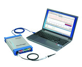
Pico Technology is a British manufacturer of high-precision PC-based oscilloscopes and automotive diagnostics equipment, founded in 1991. Their product range includes the PicoScope line of PC-based oscilloscopes, data loggers, automotive equipment, and most recently, handheld USB-based oscilloscopes. Since their inception in 1991, Pico Tech has been researching and developing PC-based oscilloscopes, when the market standard was analogue storage oscilloscopes. Pico Technology is one of two European scope manufacturers, and competes in the low to middle end of the instrumentation market.

