Transformer ratio arm bridge

Last updated

The transformer ratio arm bridge or TRA bridge is a type of bridge circuit for measuring electronic components, using a.c. It can be designed to work in terms of either impedance or admittance. It can be used on resistors, capacitors and inductors, measuring minor as well as major terms, e.g. series resistance in capacitors. It is probably the most accurate type of bridge available, being capable of the precision needed, for example, when checking secondary component standards against national standards. [1]

Contents

Like all bridges, the TRA bridge involves comparing an unknown component against a standard. Like all a.c. bridges, it requires a signal source and a null detector. The accuracy of this class of bridge depends on the ratio of the turns on one or more transformers. A notable advantage is that normal stray capacitance across the transformer, including lead capacitance, may affect the sensitivity of the bridge but does not affect its measuring accuracy. [2]

History

Fig. 1: Blumlein's capacitance bridge TRA bridge 1.svg
Fig. 1: Blumlein's capacitance bridge

The invention of the TRA bridge is credited to Alan Blumlein in his UK patent 323037 (published 1929), [3] and this class of bridge is sometimes known as a Blumlein bridge, although links to earlier types of bridge can be seen. Blumlein's first patent was for a capacitance-measuring bridge: Fig. 1 is redrawn from one of the diagrams in the patent.

Subsequently the ratio arm principle was applied more generally, to other classes of electronic components and at frequencies up to r.f., and with many variations in how the unknown component was connected to the transformer or transformers. [4]

Blumlein himself was responsible for several further related patents. [5] He made his first bridge while employed by the British company Standard Telephones and Cables, which did not manufacture test instruments. TRA bridges have since been made by many specialist manufacturers, [1] including Boonton, ESI (formerly Brown Engineering and BECO), General Radio, Marconi Instruments, H. W. Sullivan (now part of Megger) and Wayne Kerr. [6]

Principle

Fig. 2: Basic principle of the transformer ratio arm bridge TRA bridge 2.svg
Fig. 2: Basic principle of the transformer ratio arm bridge

One possible configuration using two transformers is shown in Fig. 2. [7] (The two transformers allow both the signal source and the null detector to be isolated from the measured component.) The unknown and the standard are both driven by T1, feeding currents to the primary of T2. Because of the winding sense of the two halves of the T2 primary, these currents are in antiphase.

If and have the same value and are fed from the same tap on T1, the antiphase currents cancel out perfectly and the null detector will show balance. When and are unequal, balance can be approached by connecting to a different tap on the T1 secondary. An exact balance may be achieved by using two or more standards connected to suitable taps.

Fig. 2 shows and as single components. Fig. 3 shows separate standards for conductance and susceptance , allowing minor as well as major terms of to be resolved. [2] The standards are shown as variable components connected to fixed taps on the T1 secondary, but bridges can equally be made with fixed standards connected to variable taps.

The unknown component too may be connected to a tap part-way along the T1 secondary. Also the numbers of turns on the two arms of the T1 secondary are not necessarily equal, and likewise those on the T2 primary. Combinations of these various options offer great flexibility of construction, allowing measurements over a wide range of values while using only a small number of standards – essentially one per significant figure of the resistance or conductance value and one per significant figure of the reactance or susceptance value. [8]

Fig. 3: Transformer ratio arm bridge with separate conductance and susceptance standards TRA bridge 3.svg
Fig. 3: Transformer ratio arm bridge with separate conductance and susceptance standards

In Fig. 3, [2] at balance

The bridge may be balanced (nulled) by manual switching of the standards, but "autobalance" bridges, in which the switching is wholly or partially automated, are also made.

Detailed example

The operation of a universal TRA bridge [8] is best explained on the basis of an actual product, the Wayne Kerr B221 bridge, dating from the 1950s. [7] It used valve (vacuum tube) technology. The following description is simplified.

Fig. 4: Wide-range transformer ratio arm bridge in detail TRA bridge 4.svg
Fig. 4: Wide-range transformer ratio arm bridge in detail

The bridge is based on two transformers (Fig. 4): T1 is described as the voltage transformer, and is driven by the signal source in the usual way. T2, the "current transformer", compares the two arms of the circuit for the unknown and the various standards and drives the null detector, which takes the form of a phase-sensitive detector with adjustable sensitivity, feeding two magic eyes. (Later versions of the instrument, with transistorised circuitry, used a moving-coil meter as the display for the null detector.)

Taps at 1, 10, 100 and 1000 turns are shown on the T1 secondary and on T2 primary P2a. Four-way selector switches are shown, but the tap selections are actually combined on a single switch to give seven measuring ranges. Full-scale limits at full accuracy (specified as ±0.1%) are 100 MΩ, 11.1 pF and 10 kH for the least sensitive range, and 100 Ω, 11.1 µF and 10 mH for the most sensitive range. Each range can be extended in the direction of higher resistance, higher inductance or lower capacitance at reduced accuracy. The voltage applied by T1 to is about 30 V r.m.s. on the least sensitive range, 30 mV on the two most sensitive.

The most significant figures of the major and minor components of are obtained by switching the resistance standard Rs1 and the capacitance standard Cs1 to one of taps 0 to 10 on the secondary of T1. The second significant figures are obtained by switching Rs2 and Cs2 in the same way. Continuous ("vernier") fine adjustment to give third and fourth significant figures is provided by Rs3 and Cs3. Rs3 and Cs3 are shown connected to tap 10 on T1, but in practice these two standards may be connected to any convenient tap, as appropriate to their values.

Primary P2b on T2 provides 100-turn taps of both polarities. Switching the capacitance standards between the positive and negative taps selects between capacitance measurements and inductance measurements. Similarly the polarity of the resistance standard can be reversed, so that measurements can be made in all four quadrants.

Besides the main balance controls described above, the front panel of the instrument has zero adjustments for both resistance and capacitance. The inductive elements of the wire-wound resistance standards are compensated by trimming capacitors. All these and other trimming components are omitted in Fig. 4.

This bridge measures conductance and susceptance in parallel. The susceptance reading is displayed as capacitance, and inductance must be calculated as a reciprocal using

To simplify the arithmetic, the bridge operates at 1592 Hz so that ω2 is 108 s2. The readings can be converted to resistance and capacitance in series. On the most sensitive ranges, readings must be adjusted to take account of lead resistance and inductance.

The external link allows two-, three- or four-terminal measurements to be made. Besides conventional component measurements, the bridge can also be used to measure attenuator performance, transformer turns ratio and the effectiveness of transformer screening. Subject to conditions, in-situ (in-circuit) measurement of a component is possible. With additional external components, capacitors with a polarising voltage or inductors with a standing direct current can be measured.

An optional low-impedance adaptor extends the measuring range downwards by another four orders of magnitude, giving full-scale readings down to 10 mΩ, 5 F and 1 µH at ±1% basic accuracy.

See also

Related Research Articles

<span class="mw-page-title-main">Electrical impedance</span> Opposition of a circuit to a current when a voltage is applied

In electrical engineering, impedance is the opposition to alternating current presented by the combined effect of resistance and reactance in a circuit.

<span class="mw-page-title-main">Rectifier</span> Electrical device that converts AC to DC

A rectifier is an electrical device that converts alternating current (AC), which periodically reverses direction, to direct current (DC), which flows in only one direction. The reverse operation is performed by an inverter.

In electrical engineering, admittance is a measure of how easily a circuit or device will allow a current to flow. It is defined as the reciprocal of impedance, analogous to how conductance and resistance are defined. The SI unit of admittance is the siemens ; the older, synonymous unit is mho, and its symbol is ℧. Oliver Heaviside coined the term admittance in December 1887. Heaviside used Y to represent the magnitude of admittance, but it quickly became the conventional symbol for admittance itself through the publications of Charles Proteus Steinmetz. Heaviside probably chose Y simply because it is next to Z in the alphabet, the conventional symbol for impedance.

In electrical engineering, susceptance is the imaginary part of admittance, where the real part is conductance. The reciprocal of admittance is impedance, where the imaginary part is reactance and the real part is resistance. In SI units, susceptance is measured in siemens (S).

<span class="mw-page-title-main">Voltage divider</span> Linear circuit that produces an output voltage that is a fraction of its input voltage

In electronics, a voltage divider (also known as a potential divider) is a passive linear circuit that produces an output voltage (Vout) that is a fraction of its input voltage (Vin). Voltage division is the result of distributing the input voltage among the components of the divider. A simple example of a voltage divider is two resistors connected in series, with the input voltage applied across the resistor pair and the output voltage emerging from the connection between them.

<span class="mw-page-title-main">Antenna tuner</span> Telecommunications device

An antenna tuner is an electronic device inserted into the feedline between a radio transmitter and its antenna. Its purpose is to optimize power transfer by matching the impedance of the radio to the impedance of the end of the feedline connecting the antenna to the transmitter.

A Colpitts oscillator, invented in 1918 by Canadian-American engineer Edwin H. Colpitts, is one of a number of designs for LC oscillators, electronic oscillators that use a combination of inductors (L) and capacitors (C) to produce an oscillation at a certain frequency. The distinguishing feature of the Colpitts oscillator is that the feedback for the active device is taken from a voltage divider made of two capacitors in series across the inductor.

<span class="mw-page-title-main">Pulse-forming network</span>

A pulse-forming network (PFN) is an electric circuit that accumulates electrical energy over a comparatively long time, and then releases the stored energy in the form of a relatively square pulse of comparatively brief duration for various pulsed power applications. In a PFN, energy storage components such as capacitors, inductors or transmission lines are charged by means of a high-voltage power source, then rapidly discharged into a load through a high-voltage switch, such as a spark gap or hydrogen thyratron. Repetition rates range from single pulses to about 104 per second. PFNs are used to produce uniform electrical pulses of short duration to power devices such as klystron or magnetron tube oscillators in radar sets, pulsed lasers, particle accelerators, flashtubes, and high-voltage utility test equipment.

<span class="mw-page-title-main">Center tap</span> Contact made to a point halfway along a winding of a transformer or inductor

In electronics, a center tap (CT) is a contact made to a point halfway along a winding of a transformer or inductor, or along the element of a resistor or a potentiometer.

<span class="mw-page-title-main">Electronic component</span> Discrete device in an electronic system

An electronic component is any basic discrete device or physical entity in an electronic system used to affect electrons or their associated fields. Electronic components are mostly industrial products, available in a singular form and are not to be confused with electrical elements, which are conceptual abstractions representing idealized electronic components and elements.

<span class="mw-page-title-main">Capacitor</span> Passive two-terminal electronic component that stores electrical energy in an electric field

A capacitor is a device that stores electrical energy in an electric field by accumulating electric charges on two closely spaced surfaces that are insulated from each other. It is a passive electronic component with two terminals.

<span class="mw-page-title-main">Maxwell bridge</span>

A Maxwell bridge is a modification to a Wheatstone bridge used to measure an unknown inductance in terms of calibrated resistance and inductance or resistance and capacitance. When the calibrated components are a parallel resistor and capacitor, the bridge is known as a Maxwell bridge. It is named for James C. Maxwell, who first described it in 1873.

<span class="mw-page-title-main">Capacitance meter</span> Type of electronic test equipment

A capacitance meter is a piece of electronic test equipment used to measure capacitance, mainly of discrete capacitors. Depending on the sophistication of the meter, it may display the capacitance only, or it may also measure a number of other parameters such as leakage, equivalent series resistance (ESR), and inductance. For most purposes and in most cases the capacitor must be disconnected from circuit; ESR can usually be measured in circuit.

<span class="mw-page-title-main">Test probe</span>

A test probe is a physical device used to connect electronic test equipment to a device under test (DUT). Test probes range from very simple, robust devices to complex probes that are sophisticated, expensive, and fragile. Specific types include test prods, oscilloscope probes and current probes. A test probe is often supplied as a test lead, which includes the probe, cable and terminating connector.

<span class="mw-page-title-main">Transformer types</span> Overview of electrical transformer types

A variety of types of electrical transformer are made for different purposes. Despite their design differences, the various types employ the same basic principle as discovered in 1831 by Michael Faraday, and share several key functional parts.

<span class="mw-page-title-main">LCR meter</span> Electronic test equipment that measures inductance, capacitance, and resistance

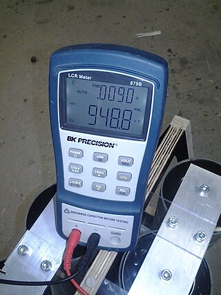
An LCR meter is a type of electronic test equipment used to measure the inductance (L), capacitance (C), and resistance (R) of an electronic component. In the simpler versions of this instrument the impedance was measured internally and converted for display to the corresponding capacitance or inductance value. Readings should be reasonably accurate if the capacitor or inductor device under test does not have a significant resistive component of impedance. More advanced designs measure true inductance or capacitance, as well as the equivalent series resistance of capacitors and the Q factor of inductive components.

<span class="mw-page-title-main">Gyrator–capacitor model</span> Model for magnetic circuits

The gyrator–capacitor model - sometimes also the capacitor-permeance model - is a lumped-element model for magnetic circuits, that can be used in place of the more common resistance–reluctance model. The model makes permeance elements analogous to electrical capacitance rather than electrical resistance. Windings are represented as gyrators, interfacing between the electrical circuit and the magnetic model.

<span class="mw-page-title-main">ESR meter</span> Tool for measuring equivalent series resistance of capacitors

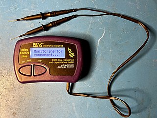
An ESR meter is a two-terminal electronic measuring instrument designed and used primarily to measure the equivalent series resistance (ESR) of real capacitors; usually without the need to disconnect the capacitor from the circuit it is connected to. Other types of meters used for routine servicing, including normal capacitance meters, cannot be used to measure a capacitor's ESR, although combined meters are available that measure both ESR and out-of-circuit capacitance. A standard (DC) milliohmmeter or multimeter cannot be used to measure ESR, because a steady direct current cannot be passed through the capacitor. Most ESR meters can also be used to measure non-inductive low-value resistances, whether or not associated with a capacitor; this leads to several additional applications described below.

<span class="mw-page-title-main">Voltage transformer</span>

Voltage transformers (VT), also called potential transformers (PT), are a parallel-connected type of instrument transformer. They are designed to present a negligible load to the supply being measured and have an accurate voltage ratio and phase relationship to enable accurate secondary connected metering.

<span class="mw-page-title-main">Anderson's bridge</span>

In electronics, Anderson's bridge is a bridge circuit used to measure the self-inductance of the coil. It enables measurement of inductance by utilizing other circuit components like resistors and capacitors.

References

  1. 1 2 Hall, Part IV.
  2. 1 2 3 B. Rogal, Recent Advances in Three-Terminal Bridge Techniques, Proc. Inst. of Electronics, Vol. 4, no. 2 (1961) 8–14.
  3. "Espacenet – search results".
  4. Hall, Parts III and IV.
  5. UK patents with year of publication: 338588 (1930), 541942 (1941), 581161 (1946), 581164 (1946), 585789 (1947), 587878 (1947).
  6. Wayne Kerr website
  7. 1 2 B221 brochure.
  8. 1 2 R. Calvert, The Transformer Ratio-Arm Bridge, Wayne Kerr Monograph No. 1 (no date).

Further reading

Henry P. Hall, A History of Impedance Measurements, based on a draft for an unpublished book.