In classical mechanics, a harmonic oscillator is a system that, when displaced from its equilibrium position, experiences a restoring force F proportional to the displacement x:

An inductor, also called a coil, choke, or reactor, is a passive two-terminal electrical component that stores energy in a magnetic field when electric current flows through it. An inductor typically consists of an insulated wire wound into a coil.

A Wheatstone bridge is an electrical circuit used to measure an unknown electrical resistance by balancing two legs of a bridge circuit, one leg of which includes the unknown component. The primary benefit of the circuit is its ability to provide extremely accurate measurements. Its operation is similar to the original potentiometer.
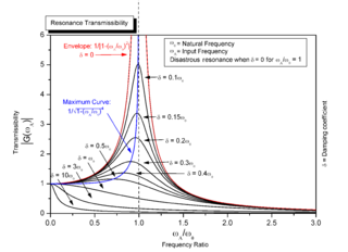
Resonance describes the phenomenon of increased amplitude that occurs when the frequency of a periodically applied force is equal or close to a natural frequency of the system on which it acts. When an oscillating force is applied at a resonant frequency of a dynamical system, the system will oscillate at a higher amplitude than when the same force is applied at other, non-resonant frequencies.
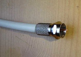
In electrical engineering, a transmission line is a specialized cable or other structure designed to conduct electromagnetic waves in a contained manner. The term applies when the conductors are long enough that the wave nature of the transmission must be taken into account. This applies especially to radio-frequency engineering because the short wavelengths mean that wave phenomena arise over very short distances. However, the theory of transmission lines was historically developed to explain phenomena on very long telegraph lines, especially submarine telegraph cables.

In electrical engineering, electrical impedance is the measure of the opposition that a circuit presents to a current when a voltage is applied.
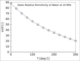
The relative permittivity, or dielectric constant, of a material is its (absolute) permittivity expressed as a ratio relative to the vacuum permittivity.
Capacitance is the ratio of the amount of electric charge stored on a conductor to a difference in electric potential. There are two closely related notions of capacitance: self capacitance and mutual capacitance. Any object that can be electrically charged exhibits self capacitance. In this case the electric potential difference is measured between the object and ground. A material with a large self capacitance holds more electric charge at a given potential difference than one with low capacitance. The notion of mutual capacitance is particularly important for understanding the operations of the capacitor, one of the three elementary linear electronic components. In a typical capacitor, two conductors are used to separate electric charge, with one conductor being positively charged and the other negatively charged, but the system having a total charge of zero. The ratio in this case is the magnitude of the electric charge on either conductor and the potential difference is that measured between the two conductors.

In physics, angular frequencyω is a scalar measure of rotation rate. It refers to the angular displacement per unit time or the rate of change of the phase of a sinusoidal waveform, or as the rate of change of the argument of the sine function. Angular frequency is the magnitude of the vector quantity angular velocity.
In electrical engineering, susceptance (B) is the imaginary part of admittance, where the real part is conductance. The reciprocal of admittance is impedance, where the imaginary part is reactance and the real part is resistance. In SI units, susceptance is measured in siemens.

In electronics, a voltage divider is a passive linear circuit that produces an output voltage (Vout) that is a fraction of its input voltage (Vin). Voltage division is the result of distributing the input voltage among the components of the divider. A simple example of a voltage divider is two resistors connected in series, with the input voltage applied across the resistor pair and the output voltage emerging from the connection between them.
A bridge circuit is a topology of electrical circuitry in which two circuit branches are "bridged" by a third branch connected between the first two branches at some intermediate point along them. The bridge was originally developed for laboratory measurement purposes and one of the intermediate bridging points is often adjustable when so used. Bridge circuits now find many applications, both linear and non-linear, including in instrumentation, filtering and power conversion.

A Wien bridge oscillator is a type of electronic oscillator that generates sine waves. It can generate a large range of frequencies. The oscillator is based on a bridge circuit originally developed by Max Wien in 1891 for the measurement of impedances. The bridge comprises four resistors and two capacitors. The oscillator can also be viewed as a positive gain amplifier combined with a bandpass filter that provides positive feedback. Automatic gain control, intentional non-linearity and incidental non-linearity limit the output amplitude in various implementations of the oscillator.

A capacitor is a device that stores electric charge in an electric field. It is a passive electronic component with two terminals.

A Maxwell bridge is a modification to a Wheatstone bridge used to measure an unknown inductance in terms of calibrated resistance and inductance or resistance and capacitance. When the calibrated components are a parallel resistor and capacitor, the bridge is known as a Maxwell-Wien bridge. It is named for James C. Maxwell, who first described it in 1873.
The telegrapher's equations are a pair of coupled, linear partial differential equations that describe the voltage and current on an electrical transmission line with distance and time. The equations come from Oliver Heaviside who developed the transmission line model starting with an August 1876 paper, On the Extra Current. The model demonstrates that the electromagnetic waves can be reflected on the wire, and that wave patterns can form along the line.

Electronic filter topology defines electronic filter circuits without taking note of the values of the components used but only the manner in which those components are connected.

Zobel networks are a type of filter section based on the image-impedance design principle. They are named after Otto Zobel of Bell Labs, who published a much-referenced paper on image filters in 1923. The distinguishing feature of Zobel networks is that the input impedance is fixed in the design independently of the transfer function. This characteristic is achieved at the expense of a much higher component count compared to other types of filter sections. The impedance would normally be specified to be constant and purely resistive. For this reason, Zobel networks are also known as constant resistance networks. However, any impedance achievable with discrete components is possible.
A Kelvin bridge, also called a Kelvin double bridge and in some countries a Thomson bridge, is a measuring instrument used to measure unknown electrical resistors below 1 ohm. It is specifically designed to measure resistors that are constructed as four terminal resistors.
Electrical capacitance volume tomography (ECVT) is a non-invasive 3D imaging technology applied primarily to multiphase flows. It was first introduced by W. Warsito, Q. Marashdeh, and L.-S. Fan as an extension of the conventional electrical capacitance tomography (ECT). In conventional ECT, sensor plates are distributed around a surface of interest. Measured capacitance between plate combinations is used to reconstruct 2D images (tomograms) of material distribution. In ECT, the fringing field from the edges of the plates is viewed as a source of distortion to the final reconstructed image and is thus mitigated by guard electrodes. ECVT exploits this fringing field and expands it through 3D sensor designs that deliberately establish an electric field variation in all three dimensions. The image reconstruction algorithms are similar in nature to ECT; nevertheless, the reconstruction problem in ECVT is more complicated. The sensitivity matrix of an ECVT sensor is more ill-conditioned and the overall reconstruction problem is more ill-posed compared to ECT. The ECVT approach to sensor design allows direct 3D imaging of the outrounded geometry. This is different than 3D-ECT that relies on stacking images from individual ECT sensors. 3D-ECT can also be accomplished by stacking frames from a sequence of time intervals of ECT measurements. Because the ECT sensor plates are required to have lengths on the order of the domain cross-section, 3D-ECT does not provide the required resolution in the axial dimension. ECVT solves this problem by going directly to the image reconstruction and avoiding the stacking approach. This is accomplished by using a sensor that is inherently three-dimensional.


