
Electrical impedance is the measure of the opposition that a circuit presents to a current when a voltage is applied. The term complex impedance may be used interchangeably.
In electric and electronic systems, reactance is the opposition of a circuit element to the flow of current due to that element's inductance or capacitance. Larger reactance leads to smaller currents for the same voltage applied. Reactance is similar to electric resistance, but it differs in several respects.
Electrical elements are conceptual abstractions representing idealized electrical components, such as resistors, capacitors, and inductors, used in the analysis of electrical networks. All electrical networks can be analyzed as multiple electrical elements interconnected by wires. Where the elements roughly correspond to real components the representation can be in the form of a schematic diagram or circuit diagram. This is called a lumped-element circuit model. In other cases infinitesimal elements are used to model the network, in a distributed-element model.
An electrolytic capacitor is a polarized capacitor whose anode or positive plate is made of a metal that forms an insulating oxide layer through anodization. This oxide layer acts as the dielectric of the capacitor. A solid, liquid, or gel electrolyte covers the surface of this oxide layer, serving as the cathode or negative plate of the capacitor. Due to their very thin dielectric oxide layer and enlarged anode surface, electrolytic capacitors have a much higher capacitance-voltage (CV) product per unit volume than ceramic capacitors or film capacitors, and so can have large capacitance values. There are three families of electrolytic capacitor: aluminum electrolytic capacitors, tantalum electrolytic capacitors, and niobium electrolytic capacitors.

In electronics, a voltage divider is a passive linear circuit that produces an output voltage (Vout) that is a fraction of its input voltage (Vin). Voltage division is the result of distributing the input voltage among the components of the divider. A simple example of a voltage divider is two resistors connected in series, with the input voltage applied across the resistor pair and the output voltage emerging from the connection between them.
Practical capacitors and inductors as used in electric circuits are not ideal components with only capacitance or inductance. However, they can be treated, to a very good degree of approximation, as being ideal capacitors and inductors in series with a resistance; this resistance is defined as the equivalent series resistance (ESR). If not otherwise specified, the ESR is always an AC resistance, which means it is measured at specified frequencies, 100 kHz for switched-mode power supply components, 120 Hz for linear power-supply components, and at its self-resonant frequency for general-application components. Additionally, audio components may report a "Q factor", incorporating ESR among other things, at 1000 Hz.
A Colpitts oscillator, invented in 1918 by American engineer Edwin H. Colpitts, is one of a number of designs for LC oscillators, electronic oscillators that use a combination of inductors (L) and capacitors (C) to produce an oscillation at a certain frequency. The distinguishing feature of the Colpitts oscillator is that the feedback for the active device is taken from a voltage divider made of two capacitors in series across the inductor.

An electronic component is any basic discrete device or physical entity in an electronic system used to affect electrons or their associated fields. Electronic components are mostly industrial products, available in a singular form and are not to be confused with electrical elements, which are conceptual abstractions representing idealized electronic components.
Equivalent series inductance (ESL) is an effective inductance that is used to describe the inductive part of the impedance of certain electrical components.

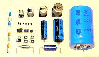
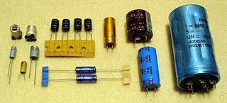
Capacitors are manufactured in many forms, styles, lengths, girths, and from many materials. They all contain at least two electrical conductors separated by an insulating layer. Capacitors are widely used as parts of electrical circuits in many common electrical devices.

Electrical resonance occurs in an electric circuit at a particular resonant frequency when the impedances or admittances of circuit elements cancel each other. In some circuits, this happens when the impedance between the input and output of the circuit is almost zero and the transfer function is close to one.

A capacitor is a device that stores electrical energy in an electric field. It is a passive electronic component with two terminals.

A Maxwell bridge is a modification to a Wheatstone bridge used to measure an unknown inductance in terms of calibrated resistance and inductance or resistance and capacitance. When the calibrated components are a parallel resistor and capacitor, the bridge is known as a Maxwell-Wien bridge. It is named for James C. Maxwell, who first described it in 1873.

A ceramic capacitor is a fixed-value capacitor where the ceramic material acts as the dielectric. It is constructed of two or more alternating layers of ceramic and a metal layer acting as the electrodes. The composition of the ceramic material defines the electrical behavior and therefore applications. Ceramic capacitors are divided into two application classes:

The Wien bridge is a type of bridge circuit that was developed by Max Wien in 1891. The bridge consists of four resistors and two capacitors.

An LCR meter is a type of electronic test equipment used to measure the inductance (L), capacitance (C), and resistance (R) of an electronic component. In the simpler versions of this instrument the impedance was measured internally and converted for display to the corresponding capacitance or inductance value. Readings should be reasonably accurate if the capacitor or inductor device under test does not have a significant resistive component of impedance. More advanced designs measure true inductance or capacitance, as well as the equivalent series resistance of capacitors and the Q factor of inductive components.

A tantalum electrolytic capacitor is an electrolytic capacitor, a passive component of electronic circuits. It consists of a pellet of porous tantalum metal as an anode, covered by an insulating oxide layer that forms the dielectric, surrounded by liquid or solid electrolyte as a cathode. Because of its very thin and relatively high permittivity dielectric layer, the tantalum capacitor distinguishes itself from other conventional and electrolytic capacitors in having high capacitance per volume and lower weight.

The gyrator–capacitor model - sometimes also the capacitor-permeance model - is a lumped-element model for magnetic circuits, that can be used in place of the more common resistance–reluctance model. The model makes permeance elements analogous to electrical capacitance rather than electrical resistance. Windings are represented as gyrators, interfacing between the electrical circuit and the magnetic model.

Film capacitors, plastic film capacitors, film dielectric capacitors, or polymer film capacitors, generically called "film caps" as well as power film capacitors, are electrical capacitors with an insulating plastic film as the dielectric, sometimes combined with paper as carrier of the electrodes.
Aluminium electrolytic capacitors are polarized electrolytic capacitors whose anode electrode (+) is made of a pure aluminum foil with an etched surface. The aluminum forms a very thin insulating layer of aluminium oxide by anodization that acts as the dielectric of the capacitor. A non-solid electrolyte covers the rough surface of the oxide layer, serving in principle as the second electrode (cathode) (-) of the capacitor. A second aluminum foil called “cathode foil” contacts the electrolyte and serves as the electrical connection to the negative terminal of the capacitor.
