An electronic oscillator is an electronic circuit that produces a periodic, oscillating electronic signal, often a sine wave or a square wave or a triangle wave. They convert direct current (DC) from a power supply to an alternating current (AC) signal. They are widely used in many electronic devices ranging from the simplest clock generators to digital instruments and complex computers and peripherals etc. Common examples of signals generated by oscillators include signals broadcast by radio and television transmitters, clock signals that regulate computers and quartz clocks, and the sounds produced by electronic beepers and video games.
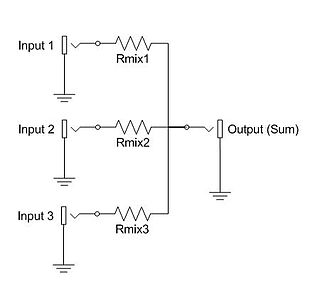
An electronic mixer is a device that combines two or more electrical or electronic signals into one or two composite output signals. There are two basic circuits that both use the term mixer, but they are very different types of circuits: additive mixers and multiplicative mixers. Additive mixers are also known as analog adders to distinguish from the related digital adder circuits.
In engineering, a transfer function of a system, sub-system, or component is a mathematical function that models the system's output for each possible input. They are widely used in electronic engineering tools like circuit simulators and control systems. In some simple cases, this function can be represented as two-dimensional graph of an independent scalar input versus the dependent scalar output, called a transfer curve or characteristic curve. Transfer functions for components are used to design and analyze systems assembled from components, particularly using the block diagram technique, in electronics and control theory.
In signal processing, distortion is the alteration of the original shape of a signal. In communications and electronics it means the alteration of the waveform of an information-bearing signal, such as an audio signal representing sound or a video signal representing images, in an electronic device or communication channel.

A phase-locked loop or phase lock loop (PLL) is a control system that generates an output signal whose phase is related to the phase of an input signal. There are several different types; the simplest is an electronic circuit consisting of a variable frequency oscillator and a phase detector in a feedback loop. The oscillator's frequency and phase are controlled proportionally by an applied voltage, hence the term voltage-controlled oscillator (VCO). The oscillator generates a periodic signal of a specific frequency, and the phase detector compares the phase of that signal with the phase of the input periodic signal, to adjust the oscillator to keep the phases matched.
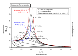
Resonance describes the phenomenon of increased amplitude that occurs when the frequency of an applied periodic force is equal or close to a natural frequency of the system on which it acts. When an oscillating force is applied at a resonant frequency of a dynamic system, the system will oscillate at a higher amplitude than when the same force is applied at other, non-resonant frequencies.
The total harmonic distortion is a measurement of the harmonic distortion present in a signal and is defined as the ratio of the sum of the powers of all harmonic components to the power of the fundamental frequency. Distortion factor, a closely related term, is sometimes used as a synonym.
Nonlinear distortion is a term used to describe the phenomenon of a non-linear relationship between the "input" and "output" signals of - for example - an electronic device.
A resistor–capacitor circuit, or RC filter or RC network, is an electric circuit composed of resistors and capacitors. It may be driven by a voltage or current source and these will produce different responses. A first order RC circuit is composed of one resistor and one capacitor and is the simplest type of RC circuit.

In electronics, a voltage divider (also known as a potential divider) is a passive linear circuit that produces an output voltage (Vout) that is a fraction of its input voltage (Vin). Voltage division is the result of distributing the input voltage among the components of the divider. A simple example of a voltage divider is two resistors connected in series, with the input voltage applied across the resistor pair and the output voltage emerging from the connection between them.

Intermodulation (IM) or intermodulation distortion (IMD) is the amplitude modulation of signals containing two or more different frequencies, caused by nonlinearities or time variance in a system. The intermodulation between frequency components will form additional components at frequencies that are not just at harmonic frequencies of either, like harmonic distortion, but also at the sum and difference frequencies of the original frequencies and at sums and differences of multiples of those frequencies.
In electronics, a frequency multiplier is an electronic circuit that generates an output signal and that output frequency is a harmonic (multiple) of its input frequency. Frequency multipliers consist of a nonlinear circuit that distorts the input signal and consequently generates harmonics of the input signal. A subsequent bandpass filter selects the desired harmonic frequency and removes the unwanted fundamental and other harmonics from the output.
A resistor–inductor circuit, or RL filter or RL network, is an electric circuit composed of resistors and inductors driven by a voltage or current source. A first-order RL circuit is composed of one resistor and one inductor, either in series driven by a voltage source or in parallel driven by a current source. It is one of the simplest analogue infinite impulse response electronic filters.
Ripple in electronics is the residual periodic variation of the DC voltage within a power supply which has been derived from an alternating current (AC) source. This ripple is due to incomplete suppression of the alternating waveform after rectification. Ripple voltage originates as the output of a rectifier or from generation and commutation of DC power.
In electronic music, waveshaping is a type of distortion synthesis in which complex spectra are produced from simple tones by altering the shape of the waveforms.
A total harmonic distortion analyzer calculates the total harmonic content of a sinewave with some distortion, expressed as total harmonic distortion (THD). A typical application is to determine the THD of an amplifier by using a very-low-distortion sinewave input and examining the output. The figure measured will include noise, and any contribution from imperfect filtering out of the fundamental frequency. Harmonic-by-harmonic measurement, without wideband noise, can be measured by a more complex wave analyser.
A linear response function describes the input-output relationship of a signal transducer, such as a radio turning electromagnetic waves into music or a neuron turning synaptic input into a response. Because of its many applications in information theory, physics and engineering there exist alternative names for specific linear response functions such as susceptibility, impulse response or impedance; see also transfer function. The concept of a Green's function or fundamental solution of an ordinary differential equation is closely related.
Spurious-free dynamic range (SFDR) is the strength ratio of the fundamental signal to the strongest spurious signal in the output. It is also defined as a measure used to specify analog-to-digital and digital-to-analog converters and radio receivers.
In an electric power system, a harmonic of a voltage or current waveform is a sinusoidal wave whose frequency is an integer multiple of the fundamental frequency. Harmonic frequencies are produced by the action of non-linear loads such as rectifiers, discharge lighting, or saturated electric machines. They are a frequent cause of power quality problems and can result in increased equipment and conductor heating, misfiring in variable speed drives, and torque pulsations in motors and generators.
Differential gain is a kind of linearity distortion that affects the amplification and transmission of analog signals. It can visibly affect color saturation in analog TV broadcasting.


