
Amplitude modulation (AM) is a modulation technique used in electronic communication, most commonly for transmitting messages with a radio wave. In amplitude modulation, the amplitude of the wave is varied in proportion to that of the message signal, such as an audio signal. This technique contrasts with angle modulation, in which either the frequency of the carrier wave is varied, as in frequency modulation, or its phase, as in phase modulation.

Analog television is the original television technology that uses analog signals to transmit video and audio. In an analog television broadcast, the brightness, colors and sound are represented by amplitude, phase and frequency of an analog signal.
Frequency modulation (FM) is the encoding of information in a carrier wave by varying the instantaneous frequency of the wave. The technology is used in telecommunications, radio broadcasting, signal processing, and computing.
In electronics and telecommunications, modulation is the process of varying one or more properties of a periodic waveform, called the carrier signal, with a separate signal called the modulation signal that typically contains information to be transmitted. For example, the modulation signal might be an audio signal representing sound from a microphone, a video signal representing moving images from a video camera, or a digital signal representing a sequence of binary digits, a bitstream from a computer.
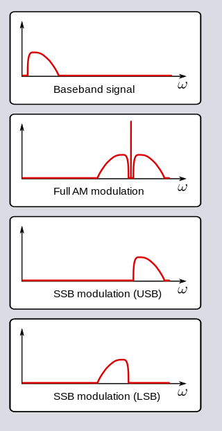
In radio communications, single-sideband modulation (SSB) or single-sideband suppressed-carrier modulation (SSB-SC) is a type of modulation used to transmit information, such as an audio signal, by radio waves. A refinement of amplitude modulation, it uses transmitter power and bandwidth more efficiently. Amplitude modulation produces an output signal the bandwidth of which is twice the maximum frequency of the original baseband signal. Single-sideband modulation avoids this bandwidth increase, and the power wasted on a carrier, at the cost of increased device complexity and more difficult tuning at the receiver.

An RF modulator is an electronic device used to convert signals from devices such as media players, VCRs and game consoles to a format that can be handled by a device designed to receive a modulated RF input, such as a radio or television receiver. Its input is a baseband signal, which is used to modulate a radio frequency source.

Pulse-width modulation (PWM), also known as pulse-duration modulation (PDM) or pulse-length modulation (PLM), is any method of representing a signal as a rectangular wave with a varying duty cycle.

Composite video is an baseband analog video format that typically carries a 525 or 625 line interlaced signal on a single channel, unlike the higher-quality S-Video and the even higher-quality component video.

Automatic gain control (AGC) is a closed-loop feedback regulating circuit in an amplifier or chain of amplifiers, the purpose of which is to maintain a suitable signal amplitude at its output, despite variation of the signal amplitude at the input. The average or peak output signal level is used to dynamically adjust the gain of the amplifiers, enabling the circuit to work satisfactorily with a greater range of input signal levels. It is used in most radio receivers to equalize the average volume (loudness) of different radio stations due to differences in received signal strength, as well as variations in a single station's radio signal due to fading. Without AGC the sound emitted from an AM radio receiver would vary to an extreme extent from a weak to a strong signal; the AGC effectively reduces the volume if the signal is strong and raises it when it is weaker. In a typical receiver the AGC feedback control signal is usually taken from the detector stage and applied to control the gain of the IF or RF amplifier stages.
This is an index of articles relating to electronics and electricity or natural electricity and things that run on electricity and things that use or conduct electricity.
Video modulation is a strategy of transmitting video signal in the field of radio modulation and television technology. This strategy enables the video signal to be transmitted more efficiently through long distances. In general, video modulation means that a higher frequency carrier wave is modified according to the original video signal. In this way, carrier wave contains the information in the video signal. Then, the carrier will "carry" the information in the form of radio frequency (RF) signal. When carrier reaches its destination, the video signal is extracted from the carrier by decoding. In other words, the video signal is first combined with a higher frequency carrier wave so that carrier wave contains the information in video signal. The combined signal is called radio-frequency signal. At the end of this transmitting system, the RF signals stream from a light sensor and hence, the receivers can obtain the initial data in the original video signal.
A television transmitter is a transmitter that is used for terrestrial (over-the-air) television broadcasting. It is an electronic device that radiates radio waves that carry a video signal representing moving images, along with a synchronized audio channel, which is received by television receivers belonging to a public audience, which display the image on a screen. A television transmitter, together with the broadcast studio which originates the content, is called a television station. Television transmitters must be licensed by governments, and are restricted to a certain frequency channel and power level. They transmit on frequency channels in the VHF and UHF bands. Since radio waves of these frequencies travel by line of sight, they are limited by the horizon to reception distances of 40–60 miles depending on the height of transmitter station.
A radio transmitter or just transmitter is an electronic device which produces radio waves with an antenna. Radio waves are electromagnetic waves with frequencies between about 30 Hz and 300 GHz. The transmitter itself generates a radio frequency alternating current, which is applied to the antenna. When excited by this alternating current, the antenna radiates radio waves. Transmitters are necessary parts of all systems that use radio: radio and television broadcasting, cell phones, wireless networks, radar, two way radios like walkie talkies, radio navigation systems like GPS, remote entry systems, among numerous other uses.
A radar system uses a radio-frequency electromagnetic signal reflected from a target to determine information about that target. In any radar system, the signal transmitted and received will exhibit many of the characteristics described below.
In analogue TV technology, residual carrier is the ratio of carrier level which is modulated by the maximum video signal to the unmodulated carrier level.
A white clipper is a circuit in professional video products that limits the maximum amplitude of the luminance part of the analogue video signal to 1 volt. It is essential for both analogue recording and transmission of video material.
Differential gain is a kind of linearity distortion that affects the amplification and transmission of analog signals. It can visibly affect color saturation in analog TV broadcasting.
The following outline is provided as an overview of and topical guide to television broadcasting:
Differential phase is a kind of linearity distortion which affects the color hue in TV broadcasting.
The output power of a TV transmitter is the electric power applied to antenna system. There are two definitions: nominal and thermal. Analogue television systems put about 70% to 90% of the transmitters power into the sync pulses. The remainder of the transmitter's power goes into transmitting the video's higher frequencies and the FM audio carrier. Digital television modulation systems are about 30% more efficient than analogue modulation systems overall.
