CCIR System A

Last updated

CCIR System A was the 405-line analog broadcast television system adopted in the UK and Ireland. System A service started in 1936 and was discontinued in 1985.

Contents

Specifications

Channel spacing for CCIR television System A (VHF Bands)
The separation between the audio and video carriers is -3.5 MHz. Channel spacing for CCIR television System A (VHF Bands).svg
Channel spacing for CCIR television System A (VHF Bands)
The separation between the audio and video carriers is −3.5 MHz.

Some of the important specs are listed below.

A frame is the total picture. The frame rate is the number of pictures displayed in one second. But each frame is actually scanned twice interleaving odd and even lines. Each scan is known as a field (odd and even fields.) So field rate is twice the frame rate. In each frame there are 405 lines (or 202.5 lines in a field.) So the line rate (line frequency) is 405 times the frame frequency or 405•25=10125 Hz.

The video bandwidth was 3.0 MHz. The video signal modulates the carrier by amplitude modulation, but a portion of the upper sideband is suppressed. This technique is known as vestigial sideband modulation (AC3). The polarity of modulation is positive, meaning that an increase in the instantaneous brightness of the video signal results in an increase in RF power and vice versa. Specifically, the sync pulses (being "blacker than black") result in minimum power (possibly zero power) from the vision transmitter.

The audio signal was modulated by amplitude modulation.

The separation between the audio AM carrier and the video carrier is −3.5 MHz.

The total RF bandwidth of System A was 4.26 MHz, allowing System A to be transmitted in the 5.0 MHz wide channels specified for television in the British VHF bands with an ample 740 kHz guard zone between channels.

In specifications, sometimes, other parameters such as vestigial sideband characteristics and gamma of display device are also given.

Colour TV

System A has variously been tested with the NTSC, PAL and SECAM colour systems. However, apart from out-of-hours technical tests in the 1950s and 1960s, colour was never transmitted officially on System A.

Colour tests were first radiated from Alexandra Palace from 7 October 1954. [3] When testing with NTSC between November 1956 and April 1958, the colour subcarrier was 2.6578125 MHz with a 'Q' bandwidth of 340 kHz (matching the rolloff of the luminance signal at +3.0 MHz). On the low-frequency side, a full 1.0 MHz single-sideband of the 'I' signal was radiated. [4]

When testing with PAL, the colour subcarrier was 2.66034375 MHz and the sidebands of the PAL signal had to be truncated on the high-frequency side at +330 kHz (matching the rolloff of the luminance signal at +3.0 MHz). On the low-frequency side, a full 1.0 MHz sideband was radiated. (This behaviour would cause massive U/V crosstalk in the NTSC system, but delay-line PAL hides such artefacts.)

When used with SECAM, the FM carrier was nominally 2.66 MHz with a deviation of ±250 kHz.

None of the above colour encoding systems had any effect on the bandwidth of system A as a whole.

Improved audio

No changes were made to the audio specification over the 49 years that the 405-line system was in use.
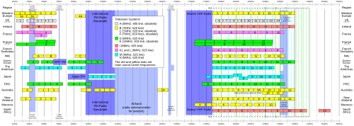
Transmission channels

Plan showing VHF frequency ranges for ITU Systems VHF Usage.svg
Plan showing VHF frequency ranges for ITU Systems

System A was the first formal broadcasting standard in the world. A European 41–68 MHz Band I television allocation was agreed at the 1947 ITU (International Telecommunication Union) conference in 1947, effectively "grandfathering in" the VHF allocation that has been used in Britain since 1936.

United Kingdom: 1936 – 1985, Ireland 1961 – 1982

ChannelChannel limits (MHz)Vision carrier frequency (MHz)Audio carrier frequency (MHz)
B1 †41.25 – 46.2545.0041.50
B248.00 – 53.0051.7548.25
B353.00 – 58.0056.7553.25
B458.00 – 63.0061.7558.25
B563.00 – 68.0066.7563.25

† Channel limits of the original transmitter at Alexandra Palace in London were 41.25 – 48.00 DSB from 1936 to 1956. Every other transmitter on channel B1 used VSB to save bandwidth and transmission power.

ChannelChannel limits (MHz)Vision carrier frequency (MHz)Audio carrier frequency (MHz)
B6176.00 – 181.00179.75176.25
B7181.00 – 186.00184.75181.25
B8186.00 – 191.00189.75186.25
B9191.00 – 196.00194.75191.25
B10196.00 – 201.00199.75196.25
B11201.00 – 206.00204.75201.25
B12206.00 – 211.00209.75206.25
B13211.00 – 216.00214.75211.25
B14 §216.00 – 221.00219.75216.25

§ Allocated, but never used.

See also

Notes and references

Related Research Articles

<span class="mw-page-title-main">Analog television</span> Television that uses analog signals

Analog television is the original television technology that uses analog signals to transmit video and audio. In an analog television broadcast, the brightness, colors and sound are represented by amplitude, phase and frequency of an analog signal.

<span class="mw-page-title-main">Chrominance</span> Colour in an image or video

Chrominance is the signal used in video systems to convey the color information of the picture, separately from the accompanying luma signal. Chrominance is usually represented as two color-difference components: U = B′ − Y′ (blue − luma) and V = R′ − Y′ (red − luma). Each of these different components may have scale factors and offsets applied to it, as specified by the applicable video standard.

<span class="mw-page-title-main">NTSC</span> Analog television system

NTSC is the first American standard for analog television, published in 1941. In 1961, it was assigned the designation System M. It is also known as EIA standard 170.

<span class="mw-page-title-main">PAL</span> Colour encoding system for analogue television

Phase Alternating Line (PAL) is a colour encoding system for analog television. It was one of three major analogue colour television standards, the others being NTSC and SECAM. In most countries it was broadcast at 625 lines, 50 fields per second, and associated with CCIR analogue broadcast television systems B, D, G, H, I or K. The articles on analog broadcast television systems further describe frame rates, image resolution, and audio modulation.

<span class="mw-page-title-main">Sideband</span> Radio communications concept

In radio communications, a sideband is a band of frequencies higher than or lower than the carrier frequency, that are the result of the modulation process. The sidebands carry the information transmitted by the radio signal. The sidebands comprise all the spectral components of the modulated signal except the carrier. The signal components above the carrier frequency constitute the upper sideband (USB), and those below the carrier frequency constitute the lower sideband (LSB). All forms of modulation produce sidebands.

<span class="mw-page-title-main">Frequency-division multiplexing</span> Signal processing technique in telecommunications

In telecommunications, frequency-division multiplexing (FDM) is a technique by which the total bandwidth available in a communication medium is divided into a series of non-overlapping frequency bands, each of which is used to carry a separate signal. This allows a single transmission medium such as a microwave radio link, cable or optical fiber to be shared by multiple independent signals. Another use is to carry separate serial bits or segments of a higher rate signal in parallel.

<span class="mw-page-title-main">Colorburst</span> Synchronisation signal in colour video

Colorburst is an analog and composite video signal generated by a video-signal generator used to keep the chrominance subcarrier synchronized in a color television signal. By synchronizing an oscillator with the colorburst at the back porch (beginning) of each scan line, a television receiver is able to restore the suppressed carrier of the chrominance (color) signals, and in turn decode the color information. The most common use of colorburst is to genlock equipment together as a common reference with a vision mixer in a television studio using a multi-camera setup.

The International Telecommunication Union uses an internationally agreed system for classifying radio frequency signals. Each type of radio emission is classified according to its bandwidth, method of modulation, nature of the modulating signal, and type of information transmitted on the carrier signal. It is based on characteristics of the signal, not on the transmitter used.

Broadcasttelevision systems are the encoding or formatting systems for the transmission and reception of terrestrial television signals.

In telecommunications, a pilot signal is a signal, usually a single frequency, transmitted over a communications system for supervisory, control, equalization, continuity, synchronization, or reference purposes.

The 405-line monochrome analogue television broadcasting system was the first fully electronic television system to be used in regular broadcasting. The number of television lines influences the image resolution, or quality of the picture.

<span class="mw-page-title-main">CCIR System M</span> Analog broadcast television system

CCIR System M, sometimes called 525–line, monochrome NTSC, NTSC-M, or CCIR-M, is the analog broadcast television system approved by the FCC for use in the United States since July 1, 1941, replacing the 441-line TV system introduced in 1938. System M comprises a total of 525 interlaced lines of video, of which 486 contain the image information, at 30 frames per second. Video is amplitude modulated and audio is frequency modulated, with a total bandwidth of 6 MHz for each channel, including a guard band.

<span class="mw-page-title-main">CCIR System B</span> 625-line analog television transmission format

CCIR System B was the 625-line VHF analog broadcast television system which at its peak was adopted by more than one hundred countries, either with PAL or SECAM colour. It is usually associated with CCIR System G for UHF broadcasts.

The following outline is provided as an overview of and topical guide to television broadcasting:

<span class="mw-page-title-main">CCIR System G</span> 625-line analog television transmission format

CCIR System G, also known as the "Gerber Standard", is an analog broadcast television system used in sixty countries around the world for UHF channels. System G is generally associated with System B for VHF.

CCIR System H is an analog broadcast television system used in Belgium, Bosnia and Herzegovina, Croatia, Malta, Slovenia and Liberia on UHF bands, paired with System B on VHF. It was associated with PAL colour.

<span class="mw-page-title-main">CCIR System I</span> 625-line analogue TV transmission format

CCIR System I is an analogue broadcast television system. It was first used in the Republic of Ireland starting in December 1961 as the 625-line broadcasting standard to be used on VHF Band I and Band III, sharing Band III with 405-line System A signals radiated in the north and east of the country. The Republic of Ireland has (slowly) extended its use of System I onto the UHF bands.

CCIR System E is an analog broadcast television system used in France and Monaco, associated with monochrome 819-line high resolution broadcasts. Transmissions started in 1949 and ended in 1985.

<span class="mw-page-title-main">CCIR System N</span> 625-line analog television transmission format

CCIR System N is an analog broadcast television system introduced in 1951 and adopted by Argentina, Paraguay and Uruguay, paired with the PAL color system (PAL-N). It was also used briefly in Brazil and Venezuela.

<span class="mw-page-title-main">CCIR System D</span> 625-line analog television transmission format

CCIR System D is an analog broadcast television system used in Bulgaria, Latvia, Lithuania, Poland, Romania, Slovakia, Czech Republic, Hungary, Albania and the People's Republic of China, Mongolia, Kyrgyzstan, North Korea, Tajikistan, Turkmenistan, Uzbekistan, Armenia, Azerbaijan, Georgia, Kazakhstan, Moldova, Russia, Ukraine and Belarus paired with the PAL/SECAM colour.