
Analog television is the original television technology that uses analog signals to transmit video and audio. In an analog television broadcast, the brightness, colors and sound are represented by amplitude, phase and frequency of an analog signal.
An electronic oscillator is an electronic circuit that produces a periodic, oscillating electronic signal, often a sine wave or a square wave or a triangle wave. They convert direct current (DC) from a power supply to an alternating current (AC) signal. They are widely used in many electronic devices ranging from the simplest clock generators to digital instruments and complex computers and peripherals etc. Common examples of signals generated by oscillators include signals broadcast by radio and television transmitters, clock signals that regulate computers and quartz clocks, and the sounds produced by electronic beepers and video games.
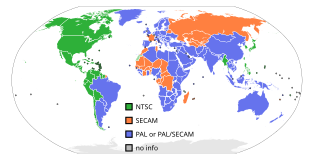
The first American standard for analog television broadcast was developed by the National Television System Committee (NTSC) in 1941. In 1961, it was assigned the designation System M.
Phase Alternating Line (PAL) is a colour encoding system for analogue television. It was one of three major analogue colour television standards, the others being NTSC and SECAM. In most countries it was broadcast at 625 lines, 50 fields per second, and associated with CCIR analogue broadcast television systems B, D, G, H, I or K. The articles on analog broadcast television systems further describe frame rates, image resolution, and audio modulation.
SECAM, also written SÉCAM, is an analog color television system that was used in France, some parts of Europe and Africa, and Russia. It was one of three major analog color television standards, the others being PAL and NTSC. This page primarily discusses the SECAM colour encoding system. The articles on broadcast television systems and analog television further describe frame rates, image resolution, and audio modulation. SECAM video is composite video because the luminance and chrominance are transmitted together as one signal.
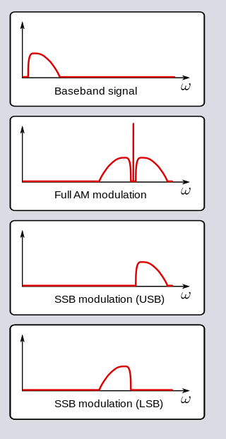
In radio communications, single-sideband modulation (SSB) or single-sideband suppressed-carrier modulation (SSB-SC) is a type of modulation used to transmit information, such as an audio signal, by radio waves. A refinement of amplitude modulation, it uses transmitter power and bandwidth more efficiently. Amplitude modulation produces an output signal the bandwidth of which is twice the maximum frequency of the original baseband signal. Single-sideband modulation avoids this bandwidth increase, and the power wasted on a carrier, at the cost of increased device complexity and more difficult tuning at the receiver.

A heterodyne is a signal frequency that is created by combining or mixing two other frequencies using a signal processing technique called heterodyning, which was invented by Canadian inventor-engineer Reginald Fessenden. Heterodyning is used to shift signals from one frequency range into another, and is also involved in the processes of modulation and demodulation. The two input frequencies are combined in a nonlinear signal-processing device such as a vacuum tube, transistor, or diode, usually called a mixer.

Colorburst is an analog video, composite video signal generated by a video-signal generator used to keep the chrominance subcarrier synchronized in a color television signal. By synchronizing an oscillator with the colorburst at the back porch (beginning) of each scan line, a television receiver is able to restore the suppressed carrier of the chrominance (color) signals, and in turn decode the color information. The most common use of colorburst is to genlock equipment together as a common reference with a vision mixer in a television studio using a multi-camera setup.
In electronics, a mixer, or frequency mixer, is an electrical circuit that creates new frequencies from two signals applied to it. In its most common application, two signals are applied to a mixer, and it produces new signals at the sum and difference of the original frequencies. Other frequency components may also be produced in a practical frequency mixer.

A Vectorscope is a special type of oscilloscope used in both audio and video applications. Whereas an oscilloscope or waveform monitor normally displays a plot of signal vs. time, a vectorscope displays an X-Y plot of two signals, which can reveal details about the relationship between these two signals. Vectorscopes are highly similar in operation to oscilloscopes operated in X-Y mode; however those used in video applications have specialized graticules, and accept standard television or video signals as input.

In signal processing, a comb filter is a filter implemented by adding a delayed version of a signal to itself, causing constructive and destructive interference. The frequency response of a comb filter consists of a series of regularly spaced notches in between regularly spaced peaks giving the appearance of a comb.
A television transmitter is a transmitter that is used for terrestrial (over-the-air) television broadcasting. It is an electronic device that radiates radio waves that carry a video signal representing moving images, along with a synchronized audio channel, which is received by television receivers belonging to a public audience, which display the image on a screen. A television transmitter, together with the broadcast studio which originates the content, is called a television station. Television transmitters must be licensed by governments, and are restricted to a certain frequency channel and power level. They transmit on frequency channels in the VHF and UHF bands. Since radio waves of these frequencies travel by line of sight, they are limited by the horizon to reception distances of 40–60 miles depending on the height of transmitter station.

A parametric oscillator is a driven harmonic oscillator in which the oscillations are driven by varying some parameter of the system at some frequency, typically different from the natural frequency of the oscillator. A simple example of a parametric oscillator is a child pumping a playground swing by periodically standing and squatting to increase the size of the swing's oscillations. The child's motions vary the moment of inertia of the swing as a pendulum. The "pump" motions of the child must be at twice the frequency of the swing's oscillations. Examples of parameters that may be varied are the oscillator's resonance frequency and damping .
In statistics, signal processing, and time series analysis, a sinusoidal model is used to approximate a sequence Yi to a sine function:
A white clipper is a circuit in professional video products that limits the maximum amplitude of the luminance part of the analogue video signal to 1 volt. It is essential for both analogue recording and transmission of video material.
Superheterodyne transmitter is a radio or TV transmitter which uses an intermediate frequency signal in addition to radio frequency signal.
In television broadcasting, VIT signals are a group of test signals inserted in the composite video signal. These signals are used to weight the transmission characteristics of the system between the test generator and the output of the demodulator, where the system includes the microwave links, or TVROs as well as the TV transmitters and the transposers. There are both ATSC and EBU standards for VIT.
Differential phase is a kind of linearity distortion which affects the color hue in TV broadcasting.
The color killer is an electronic stage in color TV receiver sets which acts as a cutting circuit to cut off color processing when the TV set receives a monochrome signal.

In continuum mechanics, Whitham's averaged Lagrangian method – or in short Whitham's method – is used to study the Lagrangian dynamics of slowly-varying wave trains in an inhomogeneous (moving) medium. The method is applicable to both linear and non-linear systems. As a direct consequence of the averaging used in the method, wave action is a conserved property of the wave motion. In contrast, the wave energy is not necessarily conserved, due to the exchange of energy with the mean motion. However the total energy, the sum of the energies in the wave motion and the mean motion, will be conserved for a time-invariant Lagrangian. Further, the averaged Lagrangian has a strong relation to the dispersion relation of the system.


