
Analog television is the original television technology that uses analog signals to transmit video and audio. In an analog television broadcast, the brightness, colors and sound are represented by amplitude, phase and frequency of an analog signal.

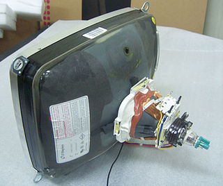
A cathode-ray tube (CRT) is a vacuum tube containing one or more electron guns, which emit electron beams that are manipulated to display images on a phosphorescent screen. The images may represent electrical waveforms on an oscilloscope, a frame of video on an analog television set (TV), digital raster graphics on a computer monitor, or other phenomena like radar targets. A CRT TV is commonly called a picture tube. CRTs have also been used as memory devices, in which case the screen is not intended to be visible to an observer. The term cathode ray was used to describe electron beams when they were first discovered, before it was understood that what was emitted from the cathode was a beam of electrons.
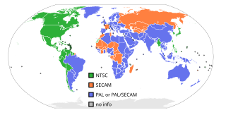
NTSC is the first American standard for analog television, published in 1941. In 1961, it was assigned the designation System M. It is also known as EIA standard.

The sawtooth wave is a kind of non-sinusoidal waveform. It is so named based on its resemblance to the teeth of a plain-toothed saw with a zero rake angle. A single sawtooth, or an intermittently triggered sawtooth, is called a ramp waveform.

Interlaced video is a technique for doubling the perceived frame rate of a video display without consuming extra bandwidth. The interlaced signal contains two fields of a video frame captured consecutively. This enhances motion perception to the viewer, and reduces flicker by taking advantage of the phi phenomenon.

In a raster scan display, the vertical blanking interval (VBI), also known as the vertical interval or VBLANK, is the time between the end of the final visible line of a frame or field and the beginning of the first visible line of the next frame or field. It is present in analog television, VGA, DVI and other signals.
Broadcasttelevision systems are the encoding or formatting systems for the transmission and reception of terrestrial television signals.
The refresh rate, also known as vertical refresh rate or vertical scan rate in reference to terminology originating with the cathode-ray tubes (CRTs), is the number of times per second that a raster-based display device displays a new image. This is independent from frame rate, which describes how many images are stored or generated every second by the device driving the display. On CRT displays, higher refresh rates produce less flickering, thereby reducing eye strain. In other technologies such as liquid-crystal displays, the refresh rate affects only how often the image can potentially be updated.

A flyback transformer (FBT), also called a line output transformer (LOPT), is a special type of electrical transformer. It was initially designed to generate high-voltage sawtooth signals at a relatively high frequency. In modern applications, it is used extensively in switched-mode power supplies for both low (3 V) and high voltage supplies.
The 405-line monochrome analogue television broadcasting system was the first fully electronic television system to be used in regular broadcasting. The number of television lines influences the image resolution, or quality of the picture.

A raster scan, or raster scanning, is the rectangular pattern of image capture and reconstruction in television. By analogy, the term is used for raster graphics, the pattern of image storage and transmission used in most computer bitmap image systems. The word raster comes from the Latin word rastrum, which is derived from radere ; see also rastrum, an instrument for drawing musical staff lines. The pattern left by the lines of a rake, when drawn straight, resembles the parallel lines of a raster: this line-by-line scanning is what creates a raster. It is a systematic process of covering the area progressively, one line at a time. Although often a great deal faster, it is similar in the most general sense to how one's gaze travels when one reads lines of text.
Coordinated Video Timings is a standard by VESA which defines the timings of the component video signal. Initially intended for use by computer monitors and video cards, the standard made its way into consumer televisions.
A multiple-sync (multisync) monitor, also known as a multiscan or multimode monitor, is a raster-scan analog video monitor that can properly synchronise with multiple horizontal and vertical scan rates. In contrast, fixed frequency monitors can only synchronise with a specific set of scan rates. They are generally used for computer displays, but sometimes for television, and the terminology is mostly applied to CRT displays although the concept applies to other technologies.
The technology of television has evolved since its early days using a mechanical system invented by Paul Gottlieb Nipkow in 1884. Every television system works on the scanning principle first implemented in the rotating disk scanner of Nipkow. This turns a two-dimensional image into a time series of signals that represent the brightness and color of each resolvable element of the picture. By repeating a two-dimensional image quickly enough, the impression of motion can be transmitted as well. For the receiving apparatus to reconstruct the image, synchronization information is included in the signal to allow proper placement of each line within the image and to identify when a complete image has been transmitted and a new image is to follow.

An oscilloscope is a type of electronic test instrument that graphically displays varying voltages of one or more signals as a function of time. Their main purpose is capturing information on electrical signals for debugging, analysis, or characterization. The displayed waveform can then be analyzed for properties such as amplitude, frequency, rise time, time interval, distortion, and others. Originally, calculation of these values required manually measuring the waveform against the scales built into the screen of the instrument. Modern digital instruments may calculate and display these properties directly.
This is a subdivision of the Oscilloscope article, discussing the various types and models of oscilloscopes in greater detail.
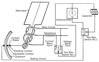
The history of the oscilloscope was fundamental to science because an oscilloscope is a device for viewing waveform oscillations, as of electrical voltage or current, in order to measure frequency and other wave characteristics. This was important in developing electromagnetic theory. The first recordings of waveforms were with a galvanometer coupled to a mechanical drawing system dating from the second decade of the 19th century. The modern day digital oscilloscope is a consequence of multiple generations of development of the oscillograph, cathode-ray tubes, analog oscilloscopes, and digital electronics.
This glossary defines terms that are used in the document "Defining Video Quality Requirements: A Guide for Public Safety", developed by the Video Quality in Public Safety (VQIPS) Working Group. It contains terminology and explanations of concepts relevant to the video industry. The purpose of the glossary is to inform the reader of commonly used vocabulary terms in the video domain. This glossary was compiled from various industry sources.
A time base generator is a special type of function generator, an electronic circuit that generates a varying voltage to produce a particular waveform. Time base generators produce very high frequency sawtooth waves specifically designed to deflect the beam of a cathode ray tube (CRT) smoothly across the face of the tube and then return it to its starting position.
A deflection yoke is a kind of magnetic lens, used in cathode ray tubes to scan the electron beam both vertically and horizontally over the whole screen.