
Amplitude modulation (AM) is a modulation technique used in electronic communication, most commonly for transmitting messages with a radio wave. In amplitude modulation, the amplitude of the wave is varied in proportion to that of the message signal, such as an audio signal. This technique contrasts with angle modulation, in which either the frequency of the carrier wave is varied, as in frequency modulation, or its phase, as in phase modulation.

Analog television is the original television technology that uses analog signals to transmit video and audio. In an analog television broadcast, the brightness, colors and sound are represented by amplitude, phase and frequency of an analog signal.

Chrominance is the signal used in video systems to convey the color information of the picture, separately from the accompanying luma signal. Chrominance is usually represented as two color-difference components: U = B′ − Y′ (blue − luma) and V = R′ − Y′ (red − luma). Each of these different components may have scale factors and offsets applied to it, as specified by the applicable video standard.
Frequency modulation (FM) is the encoding of information in a carrier wave by varying the instantaneous frequency of the wave. The technology is used in telecommunications, radio broadcasting, signal processing, and computing.
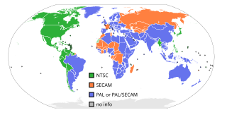
NTSC is the first American standard for analog television, published and adopted in 1941. In 1961, it was assigned the designation System M. It is also known as EIA standard 170.
Phase Alternating Line (PAL) is a colour encoding system for analog television. It was one of three major analogue colour television standards, the others being NTSC and SECAM. In most countries it was broadcast at 625 lines, 50 fields per second, and associated with CCIR analogue broadcast television systems B, D, G, H, I or K. The articles on analog broadcast television systems further describe frame rates, image resolution, and audio modulation.
SECAM, also written SÉCAM, is an analog color television system that was used in France, Russia and some other countries or territories of Europe and Africa. It was one of three major analog color television standards, the others being PAL and NTSC. Like PAL, a SECAM picture is also made up of 625 interlaced lines and is displayed at a rate of 25 frames per second. However, due to the way SECAM processes color information, it is not compatible with the PAL video format standard. SECAM video is composite video; the luminance and chrominance are transmitted together as one signal.

Colorburst is an analog and composite video signal generated by a video-signal generator used to keep the chrominance subcarrier synchronized in a color television signal. By synchronizing an oscillator with the colorburst at the back porch (beginning) of each scan line, a television receiver is able to restore the suppressed carrier of the chrominance (color) signals, and in turn decode the color information. The most common use of colorburst is to genlock equipment together as a common reference with a vision mixer in a television studio using a multi-camera setup.
A subcarrier is a sideband of a radio frequency carrier wave, which is modulated to send additional information. Examples include the provision of colour in a black and white television system or the provision of stereo in a monophonic radio broadcast. There is no physical difference between a carrier and a subcarrier; the "sub" implies that it has been derived from a carrier, which has been amplitude modulated by a steady signal and has a constant frequency relation to it.
Broadcasttelevision systems are the encoding or formatting systems for the transmission and reception of terrestrial television signals.
A television transmitter is a transmitter that is used for terrestrial (over-the-air) television broadcasting. It is an electronic device that radiates radio waves that carry a video signal representing moving images, along with a synchronized audio channel, which is received by television receivers belonging to a public audience, which display the image on a screen. A television transmitter, together with the broadcast studio which originates the content, is called a television station. Television transmitters must be licensed by governments, and are restricted to a certain frequency channel and power level. They transmit on frequency channels in the VHF and UHF bands. Since radio waves of these frequencies travel by line of sight, they are limited by the horizon to reception distances of 40–60 miles depending on the height of transmitter station.

Multiplexed Analogue Components (MAC) was an analog television standard where luminance and chrominance components were transmitted separately. This was an evolution from older color TV systems where there was interference between chrominance and luminance.
The 405-line monochrome analogue television broadcasting system was the first fully electronic television system to be used in regular broadcasting. The number of television lines influences the image resolution, or quality of the picture.
A radio transmitter or just transmitter is an electronic device which produces radio waves with an antenna. Radio waves are electromagnetic waves with frequencies between about 30 Hz and 300 GHz. The transmitter itself generates a radio frequency alternating current, which is applied to the antenna. When excited by this alternating current, the antenna radiates radio waves. Transmitters are necessary parts of all systems that use radio: radio and television broadcasting, cell phones, wireless networks, radar, two way radios like walkie talkies, radio navigation systems like GPS, remote entry systems, among numerous other uses.
Broadcast-safe video is a term used in the broadcast industry to define video and audio compliant with the technical or regulatory broadcast requirements of the target area or region the feed might be broadcasting to. In the United States, the Federal Communications Commission (FCC) is the regulatory authority; in most of Europe, standards are set by the European Broadcasting Union (EBU).
In analogue TV technology, residual carrier is the ratio of carrier level which is modulated by the maximum video signal to the unmodulated carrier level.
Differential gain is a kind of linearity distortion that affects the amplification and transmission of analog signals. It can visibly affect color saturation in analog TV broadcasting.
Zero reference pulse or Zero pulse is an artificially produced pulse in a professional television receiver imitating no radio frequency case for modulation index measurements in analogue TV transmitters.
This glossary defines terms that are used in the document "Defining Video Quality Requirements: A Guide for Public Safety", developed by the Video Quality in Public Safety (VQIPS) Working Group. It contains terminology and explanations of concepts relevant to the video industry. The purpose of the glossary is to inform the reader of commonly used vocabulary terms in the video domain. This glossary was compiled from various industry sources.
CCIR System A was the 405-line analog broadcast television system adopted in the UK and Ireland. System A service started in 1936 and was discontinued in 1985.
