Television transmitter

Last updated

A television transmitter is a transmitter that is used for terrestrial (over-the-air) television broadcasting. It is an electronic device that radiates radio waves that carry a video signal representing moving images, along with a synchronized audio channel, which is received by television receivers ('televisions' or 'TVs') belonging to a public audience, which display the image on a screen. A television transmitter, together with the broadcast studio which originates the content, is called a television station. Television transmitters must be licensed by governments, and are restricted to a certain frequency channel and power level. They transmit on frequency channels in the VHF and UHF bands. Since radio waves of these frequencies travel by line of sight, they are limited by the horizon to reception distances of 40–60 miles depending on the height of transmitter station.

Contents

Television transmitters use one of two different technologies: analog, in which the picture and sound are transmitted by analog signals modulated onto the radio carrier wave, and digital in which the picture and sound are transmitted by digital signals. The original television technology, analog television, began to be replaced in a transition beginning in 2006 in many countries with digital television (DTV) systems. These transmit pictures in a new format called HDTV (high-definition television) which has higher resolution and a wider screen aspect ratio than analog. DTV makes more efficient use of scarce radio spectrum bandwidth, as several DTV channels can be transmitted in the same bandwidth as a single analog channel. In both analog and digital television, different countries use several incompatible modulation standards to add the video and audio signals to the radio carrier wave.

The principles of primarily analog systems are summarized as they are typically more complex than digital transmitters due to the multiplexing of VSB and FM modulation stages.

Types of transmitters

There are many types of transmitters depending on

The system standard

A typical television transmitter and antenna at Karadag, Karaman, Turkey Karaman Karadag transmitting station, Turkey.jpg
A typical television transmitter and antenna at Karadağ, Karaman, Turkey

An international plan by ITU (International Telecommunication Union) on broadcast standards which is usually known as Stockholm plan (1961) defines standards used in broadcasting. In this plan, most important figures for transmitters are radio frequency, frequency separation between aural and visual carriers and band width. [1]

Input stage of a transmitter

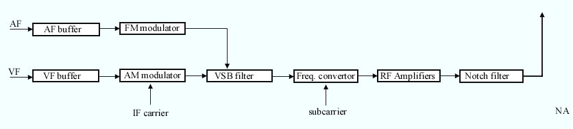
The audio (AF) input (or inputs in case of stereophonic broadcasting) is usually a signal with 15 kHz maximum bandwidth and 0 dBm maximum level. Preemphasis time constant is 50 μs. The signal after passing buffer stages is applied to a modulator, where it modulates an intermediate frequency carrier (IF). The modulation technique is usually frequency modulation (FM) with a typical maximum deviation of 50 kHz (for 1 kHz. input at 0 dBm level).

The video (VF) input is a composite video signal (video information with sync) of maximum 1 volt on 75 Ω impedance. (1 V limit is for luminance signal. Some operators may accept superimposed color signals slightly over 1 V.) After buffer and 1 V clipping circuits, the signal is applied to the modulator where it modulates an intermediate frequency signal (which is different from the one used for aural signal.) The modulator is an amplitude modulator which modulates the IF signal in a manner where 1 V VF corresponds to low level IF and 0 volt VF corresponds to high level IF. AM modulator produces two symmetrical side bands in the modulated signals. Thus, IF band width is two times the video band width. (i.e. if the VF bandwidth is 4.2 MHz, the IF bandwidth is 8.4 MHz.) However, the modulator is followed by a special filter known as Vestigal sideband (VSB) filter. This filter is used to suppress a portion of one side band, thus bandwidth is reduced. (Since both side bands contain identical information, this suppression doesn't cause a loss in information.) Although the suppression causes phase delay problems the VSB stage also includes correction circuits to equalise the phase.

Output stages

The modulated signal is applied to a mixer (also known as frequency converter). Another input to the mixer which is usually produced in a crystal oven oscillator is known as subcarrier. The two outputs of the mixer are the sum and difference of two signals. Unwanted signal (usually the sum) is filtered out and the remaining signal is the radio frequency (RF) signal. Then the signal is applied to the amplifier stages. The number of series amplifiers depends on the required output power. The final stage is usually an amplifier consisting of many parallel power transistors. But in older transmitters tetrodes or klystrons are also utilized.

In modern solid-state VHF and UHF transmitters, LDMOS power transistors are the device of choice for the output stage, with the latest products employing 50V LDMOS devices for higher efficiency and power density. Even higher energy efficiency is possible using Envelope Tracking, which in the broadcast industry is often referred to as 'drain modulation'.

Combining aural and visual signals

There are two methods:

TV transmitter diagram.jpg

Output power

The output power of the transmitter is defined as the power during sync pulse (Real output power is variable depending on the content). The quantifiable power from the transmitting equipment and antenna are different from one another. The output power of the antenna is known as ERP, which is represented by the formula

where Po represents output power, and Ga represents antenna gain.

See also

Related Research Articles

Amplitude modulation Radio modulation via wave amplitude

Amplitude modulation (AM) is a modulation technique used in electronic communication, most commonly for transmitting messages with a radio wave. In amplitude modulation, the amplitude of the wave is varied in proportion to that of the message signal, such as an audio signal. This technique contrasts with angle modulation, in which either the frequency of the carrier wave is varied, as in frequency modulation, or its phase, as in phase modulation.

<span class="mw-page-title-main">Analog television</span> Television that uses analog signals

Analog television is the original television technology that uses analog signals to transmit video and audio. In an analog television broadcast, the brightness, colors and sound are represented by amplitude, phase and frequency of an analog signal.

In electronics and telecommunications, modulation is the process of varying one or more properties of a periodic waveform, called the carrier signal, with a separate signal called the modulation signal that typically contains information to be transmitted. For example, the modulation signal might be an audio signal representing sound from a microphone, a video signal representing moving images from a video camera, or a digital signal representing a sequence of binary digits, a bitstream from a computer. The carrier is higher in frequency than the modulation signal. In radio communication the modulated carrier is transmitted through space as a radio wave to a radio receiver. Another purpose is to transmit multiple channels of information through a single communication medium, using frequency-division multiplexing (FDM). For example in cable television which uses FDM, many carrier signals, each modulated with a different television channel, are transported through a single cable to customers. Since each carrier occupies a different frequency, the channels do not interfere with each other. At the destination end, the carrier signal is demodulated to extract the information bearing modulation signal.

Single-sideband modulation Type of modulation

In radio communications, single-sideband modulation (SSB) or single-sideband suppressed-carrier modulation (SSB-SC) is a type of modulation used to transmit information, such as an audio signal, by radio waves. A refinement of amplitude modulation, it uses transmitter power and bandwidth more efficiently. Amplitude modulation produces an output signal the bandwidth of which is twice the maximum frequency of the original baseband signal. Single-sideband modulation avoids this bandwidth increase, and the power wasted on a carrier, at the cost of increased device complexity and more difficult tuning at the receiver.

Superheterodyne receiver Type of radio receiver

A superheterodyne receiver, often shortened to superhet, is a type of radio receiver that uses frequency mixing to convert a received signal to a fixed intermediate frequency (IF) which can be more conveniently processed than the original carrier frequency. It was long believed to have been invented by US engineer Edwin Armstrong, but after some controversy the earliest patent for the invention is now credited to French radio engineer and radio manufacturer Lucien Lévy. Virtually all modern radio receivers use the superheterodyne principle; except those software-defined radios using direct sampling.

Transmitter Electronic device that emits radio waves

In electronics and telecommunications, a radio transmitter or just transmitter is an electronic device which produces radio waves with an antenna. The transmitter itself generates a radio frequency alternating current, which is applied to the antenna. When excited by this alternating current, the antenna radiates radio waves.

Intermediate frequency Frequency to which a carrier wave is shifted during transmission or reception

In communications and electronic engineering, an intermediate frequency (IF) is a frequency to which a carrier wave is shifted as an intermediate step in transmission or reception. The intermediate frequency is created by mixing the carrier signal with a local oscillator signal in a process called heterodyning, resulting in a signal at the difference or beat frequency. Intermediate frequencies are used in superheterodyne radio receivers, in which an incoming signal is shifted to an IF for amplification before final detection is done.

8VSB is the modulation method used for broadcast in the ATSC digital television standard. ATSC and 8VSB modulation is used primarily in North America; in contrast, the DVB-T standard uses COFDM.

Broadcast television systems are the encoding or formatting systems for the transmission and reception of terrestrial television signals.

Amateur television

Amateur television (ATV) is the transmission of broadcast quality video and audio over the wide range of frequencies of radio waves allocated for radio amateur (Ham) use. ATV is used for non-commercial experimentation, pleasure, and public service events. Ham TV stations were on the air in many cities before commercial television stations came on the air. Various transmission standards are used, these include the broadcast transmission standards of NTSC in North America and Japan, and PAL or SECAM elsewhere, utilizing the full refresh rates of those standards. ATV includes the study of building of such transmitters and receivers, and the study of radio propagation of signals travelling between transmitting and receiving stations.

<span class="mw-page-title-main">Radio receiver</span> Radio device for receiving radio waves and converting them to a useful signal

In radio communications, a radio receiver, also known as a receiver, a wireless, or simply a radio, is an electronic device that receives radio waves and converts the information carried by them to a usable form. It is used with an antenna. The antenna intercepts radio waves and converts them to tiny alternating currents which are applied to the receiver, and the receiver extracts the desired information. The receiver uses electronic filters to separate the desired radio frequency signal from all the other signals picked up by the antenna, an electronic amplifier to increase the power of the signal for further processing, and finally recovers the desired information through demodulation.

<span class="mw-page-title-main">Tuner (radio)</span>

A tuner is a subsystem that receives radio frequency (RF) transmissions, such as FM broadcasting, and converts the selected carrier frequency and its associated bandwidth into a fixed frequency that is suitable for further processing, usually because a lower frequency is used on the output. Broadcast FM/AM transmissions usually feed this intermediate frequency (IF) directly into a demodulator that converts the radio signal into audio-frequency signals that can be fed into an amplifier to drive a loudspeaker.

A radio transmitter or just transmitter is an electronic device which produces radio waves with an antenna. Radio waves are electromagnetic waves with frequencies between about 30 Hz and 300 GHz. The transmitter itself generates a radio frequency alternating current, which is applied to the antenna. When excited by this alternating current, the antenna radiates radio waves. Transmitters are necessary parts of all systems that use radio: radio and television broadcasting, cell phones, wireless networks, radar, two way radios like walkie talkies, radio navigation systems like GPS, remote entry systems, among numerous other uses.

Valve RF amplifier Device for electrically amplifying the power of an electrical radio frequency signal

A valve RF amplifier or tube amplifier (U.S.) is a device for electrically amplifying the power of an electrical radio frequency signal.

A communications satellite's transponder is the series of interconnected units that form a communications channel between the receiving and the transmitting antennas.

A Nyquist filter is an electronic filter used in TV receivers to equalize the video characteristics. The filter is named after the Swedish–US engineer Harry Nyquist (1889–1976).

The intercarrier method is a system in television that reduces the cost of transmitters and receiver sets by processing audio and video signals together and minimizing the number of separate stages for audio and video signals.

In broadcasting, a transposer or translator is a device in or beyond the service area of a radio or television station transmitter that rebroadcasts signals to receivers which can’t properly receive the signals of the transmitter because of a physical obstruction. A translator receives the signals of the transmitter and rebroadcasts the signals to the area of poor reception. Sometimes the translator is also called a relay transmitter, rebroadcast transmitter or transposer. Since translators are used to cover a small shadowed area, their output powers are usually lower than that of the radio or television station transmitters feeding them.

The following outline is provided as an overview of and topical guide to television broadcasting:

Split sound is an old system in analog television transmitters. It has long been superseded, but transmitters working on this principle are still in use. In this system there are two almost independent transmitters, one for sound (aural) and one for picture (visual). The system requires more energy input relative to broadcast energy than the alternative system known as intercarrier system.

References

Further reading