Typically, the width of the stopband is 1 to 2 decades (that is, the highest frequency attenuated is 10 to 100 times the lowest frequency attenuated). However, in the audio band, a notch filter has high and low frequencies that may be only semitones apart. From the figure of the frequency response of an ideal band-stop filter, it's obvious that the band-stop filter is simply an inverted band-pass filter where they share same definition of bandwidth, pass band, stop band and center frequency. The attenuation should be infinite in the stop band and be zero in the two pass bands for an ideal band-stop filter. Band-stop filters are designed by the combination of a low-pass filter and a high-pass filter in a parallel configuration. Overlapping does not occur in the summation of high-pass filter and low-pass filter during the design of band-stop filter. The difference in the starting and ending frequency points causes the two filters to connect effectively without any overlapping.
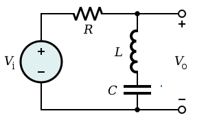
Generic electrical schematic of a simple band-stop filter
Mathematical description
Band-stop filter can be represented as a combination of low-pass and high-pass filters if the bandwidth is wide enough that the two filters do not interact too much. A more general approach is to design as a low-pass prototype filter which can then be transformed into a bandstop. The simple notch filter shown can be directly analysed. The transfer function is,
Here is zero circular frequency and is the pole circular frequency. Zero frequency is the cutoff frequency and sets the type of the notch filter: standard notch when , low-pass notch () and high-pass notch () filters. denotes the Q-factor.[2]
For standard notch filter the formulation can be rewritten as
where is the central rejected frequency and is the width of the rejected band.
This means that the filter passes all frequencies, except for the range of 59–61Hz. This would be used to filter out the mains hum from the 60Hz power line, though its higher harmonics could still be present.
For countries where power transmission is at 50Hz, the filter would have a 49–51Hz range.
In the radio-frequency (RF) domain
Non-linearities of power amplifiers
When measuring the non-linearities of power amplifiers, a very narrow notch filter can be very useful to avoid the carrier frequency. Use of the filter may ensure that the maximum input power of a spectrum analyser used to detect spurious content will not be exceeded.
Wave trap
A notch filter, usually a simple LC circuit, is used to remove a specific interfering frequency. This is a technique used with radio receivers that are so close to a transmitter that it swamps all other signals. The wave trap is used to remove or greatly reduce the signal from the nearby transmitter.[3]
Software-defined radio
Most affordable software-defined radios (SDR) on the market today suffer from limited dynamic and operating ranges. In other words, in real-world operating environments, a SDR can easily be saturated by a strong signal. In particular FM broadcast signals are very strong and nearly everywhere. These signals can prevent a SDR from processing other weak signals. FM notch filters are very useful for SDR applications and have increased in their popularity.
Optical filtering (wavelength selection)
In optics, there are several methods of filtering selected wavelengths from a source or to a detector. They rely on scattering or destructive interference.
In the case of transmission gratings and prisms, polychromatic light that passes through the object will be redirected according to wavelength. A slit may then be used to select wavelengths that are desired. A reflective grating may also be utilized for the same purpose, though in this case light is reflected rather than transmitted. Filters of this design may be high-pass, band-pass, or low-pass, depending on system configuration.
Filtering by interference
When using optics with real materials, light will be attenuated at various wavelengths through interference with the medium through which the light traversed. In this sense, material selection may be utilized to selectively filter light according to the wavelengths that are minimally attenuated. To some extent, all real optical systems will suffer from this phenomenon.
Alternatively, it is also possible to use an oscillating reflecting surface to cause destructive interference with reflected light along a single optical path. This principle is the basis for a Michelson interferometer.
Band-stop smoothing filter
Smoothing filter is essential in many fields, such as signal and image processing, computer vision, statistics, stated by Roonizi (2021).[5] Algorithms such as quadratic variation regularization and smoothness priors are the most common way to perform signal denoising. These algorithms are implemented to band-stop smoothing filters and being investigated by Roonizi (2021).[5] A naive band-stop smoothing filter is raised, which is constructed by connecting a high-pass smoothing filter and a low-pass smoothing filter. These two smoothing filter sections are configured in parallel way. Moreover, it was suggested that positive noise correlation promises to obtain the best band-stop smoothing filter.
Telecommunications
The development of telecommunications applications raises the demand of radio frequency and microwave filters, stated by Haddi (2019).[6] Those filters are commonly used in PA systems (Public Address Systems) and speaker systems to produce audio with great quality. Microwave filters have high flexibility of actualization and low cost. The band-stop filter in the telecommunications field, has a respectable place which it is essential for microwave transceivers. For example, wireless communication systems make use of band-stop filters to achieve the requirement of miniaturization.
Microstrip Band-stop Filter
Microstrip-line band-stop filter is convenient to implement with low cost and light weight. Hsieh & Wang (2005) stated that, conventional microstrip band-stop filters are made of shunt open-circuited resonators.[7] They usually has the characteristic of having narrow stopband. However, alternating the band-stop filter to have a wide stop band response with specific design can bring huge advantage over the conventional band-stop filters.
The advantages of the microstrip band-stop filter designed by Hsieh & Wang (2005) is its compact size and easy implementation. This improved band-stop filter with wide stop-band has additional amount of transmission zeros. The purpose of this design is to combine a shunt open-circuited quarter-wavelength resonator with one section of quarter-wavelength frequency-selecting coupling structure, stated by Hsieh & Wang (2005). As a result, a simple structured band-stop filter with easy implementation can bring advantages of lower-order resonators, great stop band performance when compared to conventional microstrip band-stop filters.
This page is based on this Wikipedia article Text is available under the CC BY-SA 4.0 license; additional terms may apply. Images, videos and audio are available under their respective licenses.