
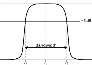
Bandwidth is the difference between the upper and lower frequencies in a continuous band of frequencies. It is typically measured in unit of hertz.
In physics and electrical engineering, a cutoff frequency, corner frequency, or break frequency is a boundary in a system's frequency response at which energy flowing through the system begins to be reduced rather than passing through.
A passband is the range of frequencies or wavelengths that can pass through a filter. For example, a radio receiver contains a bandpass filter to select the frequency of the desired radio signal out of all the radio waves picked up by its antenna. The passband of a receiver is the range of frequencies it can receive when it is tuned into the desired frequency (channel).
A low-pass filter is a filter that passes signals with a frequency lower than a selected cutoff frequency and attenuates signals with frequencies higher than the cutoff frequency. The exact frequency response of the filter depends on the filter design. The filter is sometimes called a high-cut filter, or treble-cut filter in audio applications. A low-pass filter is the complement of a high-pass filter.

A high-pass filter (HPF) is an electronic filter that passes signals with a frequency higher than a certain cutoff frequency and attenuates signals with frequencies lower than the cutoff frequency. The amount of attenuation for each frequency depends on the filter design. A high-pass filter is usually modeled as a linear time-invariant system. It is sometimes called a low-cut filter or bass-cut filter in the context of audio engineering. High-pass filters have many uses, such as blocking DC from circuitry sensitive to non-zero average voltages or radio frequency devices. They can also be used in conjunction with a low-pass filter to produce a band-pass filter.

A band-pass filter or bandpass filter (BPF) is a device that passes frequencies within a certain range and rejects (attenuates) frequencies outside that range. It's the opposite of a band-stop filter.
Chebyshev filters are analog or digital filters that have a steeper roll-off than Butterworth filters, and have either passband ripple or stopband ripple. Chebyshev filters have the property that they minimize the error between the idealized and the actual filter characteristic over the operating frequency range of the filter, but they achieve this with ripples in the passband. This type of filter is named after Pafnuty Chebyshev because its mathematical characteristics are derived from Chebyshev polynomials. Type I Chebyshev filters are usually referred to as "Chebyshev filters", while type II filters are usually called "inverse Chebyshev filters". Because of the passband ripple inherent in Chebyshev filters, filters with a smoother response in the passband but a more irregular response in the stopband are preferred for certain applications.
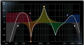
An audio filter is a frequency dependent circuit, working in the audio frequency range, 0 Hz to 20 kHz. Audio filters can amplify (boost), pass or attenuate (cut) some frequency ranges. Many types of filters exist for different audio applications including hi-fi stereo systems, musical synthesizers, effects units, sound reinforcement systems, instrument amplifiers and virtual reality systems.

In signal processing, a band-stop filter or band-rejection filter is a filter that passes most frequencies unaltered, but attenuates those in a specific range to very low levels. It is the opposite of a band-pass filter. A notch filter is a band-stop filter with a narrow stopband.

An active filter is a type of analog circuit implementing an electronic filter using active components, typically an amplifier. Amplifiers included in a filter design can be used to improve the cost, performance and predictability of a filter.
An anti-aliasing filter (AAF) is a filter used before a signal sampler to restrict the bandwidth of a signal to satisfy the Nyquist–Shannon sampling theorem over the band of interest. Since the theorem states that unambiguous reconstruction of the signal from its samples is possible when the power of frequencies above the Nyquist frequency is zero, a brick wall filter is an idealized but impractical AAF. A practical AAF makes a trade off between reduced bandwidth and increased aliasing. A practical anti-aliasing filter will typically permit some aliasing to occur or attenuate or otherwise distort some in-band frequencies close to the Nyquist limit. For this reason, many practical systems sample higher than would be theoretically required by a perfect AAF in order to ensure that all frequencies of interest can be reconstructed, a practice called oversampling.
The half-power point is the point at which the output power has dropped to half of its peak value; that is, at a level of approximately -3 dB.

The transition band, also called the skirt, is a range of frequencies that allows a transition between a passband and a stopband of a signal processing filter. The transition band is defined by a passband and a stopband cutoff frequency or corner frequency.

Electronic filter topology defines electronic filter circuits without taking note of the values of the components used but only the manner in which those components are connected.
A composite image filter is an electronic filter consisting of multiple image filter sections of two or more different types.

These filters are electrical wave filters designed using the image method. They are an invention of Otto Zobel at AT&T Corp. They are a generalisation of the m-type filter in that a transform is applied that modifies the transfer function while keeping the image impedance unchanged. For filters that have only one stopband there is no distinction with the m-type filter. However, for a filter that has multiple stopbands, there is the possibility that the form of the transfer function in each stopband can be different. For instance, it may be required to filter one band with the sharpest possible cut-off, but in another to minimise phase distortion while still achieving some attenuation. If the form is identical at each transition from passband to stopband the filter will be the same as an m-type filter. If they are different, then the general case described here pertains.
In signal processing, network synthesis filters are filters designed by the network synthesis method. The method has produced several important classes of filter including the Butterworth filter, the Chebyshev filter and the Elliptic filter. It was originally intended to be applied to the design of passive linear analogue filters but its results can also be applied to implementations in active filters and digital filters. The essence of the method is to obtain the component values of the filter from a given rational function representing the desired transfer function.
Analogue filters are a basic building block of signal processing much used in electronics. Amongst their many applications are the separation of an audio signal before application to bass, mid-range, and tweeter loudspeakers; the combining and later separation of multiple telephone conversations onto a single channel; the selection of a chosen radio station in a radio receiver and rejection of others.
In signal processing, a filter is a device or process that removes some unwanted components or features from a signal. Filtering is a class of signal processing, the defining feature of filters being the complete or partial suppression of some aspect of the signal. Most often, this means removing some frequencies or frequency bands. However, filters do not exclusively act in the frequency domain; especially in the field of image processing many other targets for filtering exist. Correlations can be removed for certain frequency components and not for others without having to act in the frequency domain. Filters are widely used in electronics and telecommunication, in radio, television, audio recording, radar, control systems, music synthesis, image processing, computer graphics, and structural dynamics.

A waffle-iron filter is a type of waveguide filter used at microwave frequencies for signal filtering. It is a variation of the corrugated-waveguide filter but with longitudinal slots cut through the corrugations resulting in an internal structure that has the appearance of a waffle-iron.
