Bandwidth is the difference between the upper and lower frequencies in a continuous band of frequencies. It is typically measured in hertz, and depending on context, may specifically refer to passband bandwidth or baseband bandwidth. Passband bandwidth is the difference between the upper and lower cutoff frequencies of, for example, a band-pass filter, a communication channel, or a signal spectrum. Baseband bandwidth applies to a low-pass filter or baseband signal; the bandwidth is equal to its upper cutoff frequency.

In physics and electrical engineering, a cutoff frequency, corner frequency, or break frequency is a boundary in a system's frequency response at which energy flowing through the system begins to be reduced rather than passing through.
A low-pass filter is a filter that passes signals with a frequency lower than a selected cutoff frequency and attenuates signals with frequencies higher than the cutoff frequency. The exact frequency response of the filter depends on the filter design. The filter is sometimes called a high-cut filter, or treble-cut filter in audio applications. A low-pass filter is the complement of a high-pass filter.

Audio crossovers are a type of electronic filter circuitry used in a range of audio applications. They split up an audio signal into two or more frequency ranges, so that the signals can be sent to loudspeaker drivers that are designed to operate within different frequency ranges. Crossovers are often described as "two-way" or "three-way", which indicate, respectively, that the crossover splits a given signal into two frequency ranges or three frequency ranges. Crossovers are used in loudspeaker cabinets, power amplifiers in consumer electronics and pro audio and musical instrument amplifier products. For the latter two markets, crossovers are used in bass amplifiers, keyboard amplifiers, bass and keyboard speaker enclosures and sound reinforcement system equipment.

In physics and engineering, the quality factor or Q factor is a dimensionless parameter that describes how underdamped an oscillator or resonator is. It is approximately defined as the ratio of the initial energy stored in the resonator to the energy lost in one radian of the cycle of oscillation. Q factor is alternatively defined as the ratio of a resonator's centre frequency to its bandwidth when subject to an oscillating driving force. These two definitions give numerically similar, but not identical, results. Higher Q indicates a lower rate of energy loss and the oscillations die out more slowly. A pendulum suspended from a high-quality bearing, oscillating in air, has a high Q, while a pendulum immersed in oil has a low one. Resonators with high quality factors have low damping, so that they ring or vibrate longer.

A band-pass filter or bandpass filter (BPF) is a device that passes frequencies within a certain range and rejects (attenuates) frequencies outside that range.

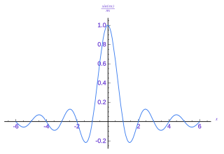
In signal processing, a sinc filter is an idealized filter that removes all frequency components above a given cutoff frequency, without affecting lower frequencies, and has linear phase response. The filter's impulse response is a sinc function in the time domain, and its frequency response is a rectangular function.

In signal processing, undersampling or bandpass sampling is a technique where one samples a bandpass-filtered signal at a sample rate below its Nyquist rate, but is still able to reconstruct the signal.

An audio filter is a frequency dependent amplifier circuit, working in the audio frequency range, 0 Hz to beyond 20 kHz. Audio filters can amplify (boost), pass or attenuate (cut) some frequency ranges. Many types of filters exist for different audio applications including hi-fi stereo systems, musical synthesizers, sound effects, sound reinforcement systems, instrument amplifiers and virtual reality systems.

The Butterworth filter is a type of signal processing filter designed to have a frequency response as flat as possible in the passband. It is also referred to as a maximally flat magnitude filter. It was first described in 1930 by the British engineer and physicist Stephen Butterworth in his paper entitled "On the Theory of Filter Amplifiers".

A voltage-controlled filter (VCF) is an electronic filter whose operating characteristics can be set by an input control voltage. Voltage controlled filters are widely used in synthesizers.
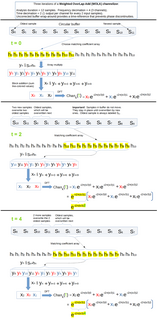
In digital signal processing, downsampling, compression, and decimation are terms associated with the process of resampling in a multi-rate digital signal processing system. Both downsampling and decimation can be synonymous with compression, or they can describe an entire process of bandwidth reduction (filtering) and sample-rate reduction. When the process is performed on a sequence of samples of a signal or a continuous function, it produces an approximation of the sequence that would have been obtained by sampling the signal at a lower rate.
In digital signal processing, upsampling, expansion, and interpolation are terms associated with the process of resampling in a multi-rate digital signal processing system. Upsampling can be synonymous with expansion, or it can describe an entire process of expansion and filtering (interpolation). When upsampling is performed on a sequence of samples of a signal or other continuous function, it produces an approximation of the sequence that would have been obtained by sampling the signal at a higher rate. For example, if compact disc audio at 44,100 samples/second is upsampled by a factor of 5/4, the resulting sample-rate is 55,125.
In signal processing, oversampling is the process of sampling a signal at a sampling frequency significantly higher than the Nyquist rate. Theoretically, a bandwidth-limited signal can be perfectly reconstructed if sampled at the Nyquist rate or above it. The Nyquist rate is defined as twice the bandwidth of the signal. Oversampling is capable of improving resolution and signal-to-noise ratio, and can be helpful in avoiding aliasing and phase distortion by relaxing anti-aliasing filter performance requirements.

In signal processing, a filter bank is an array of bandpass filters that separates the input signal into multiple components, each one carrying a single frequency sub-band of the original signal. One application of a filter bank is a graphic equalizer, which can attenuate the components differently and recombine them into a modified version of the original signal. The process of decomposition performed by the filter bank is called analysis ; the output of analysis is referred to as a subband signal with as many subbands as there are filters in the filter bank. The reconstruction process is called synthesis, meaning reconstitution of a complete signal resulting from the filtering process.

Surface roughness, often shortened to roughness, is a component of surface texture. It is quantified by the deviations in the direction of the normal vector of a real surface from its ideal form. If these deviations are large, the surface is rough; if they are small, the surface is smooth. In surface metrology, roughness is typically considered to be the high-frequency, short-wavelength component of a measured surface. However, in practice it is often necessary to know both the amplitude and frequency to ensure that a surface is fit for a purpose.

Prototype filters are electronic filter designs that are used as a template to produce a modified filter design for a particular application. They are an example of a nondimensionalised design from which the desired filter can be scaled or transformed. They are most often seen in regard to electronic filters and especially linear analogue passive filters. However, in principle, the method can be applied to any kind of linear filter or signal processing, including mechanical, acoustic and optical filters.
In signal processing, a filter is a device or process that removes some unwanted components or features from a signal. Filtering is a class of signal processing, the defining feature of filters being the complete or partial suppression of some aspect of the signal. Most often, this means removing some frequencies or frequency bands. However, filters do not exclusively act in the frequency domain; especially in the field of image processing many other targets for filtering exist. Correlations can be removed for certain frequency components and not for others without having to act in the frequency domain. Filters are widely used in electronics and telecommunication, in radio, television, audio recording, radar, control systems, music synthesis, image processing, and computer graphics.
Nominal impedance in electrical engineering and audio engineering refers to the approximate designed impedance of an electrical circuit or device. The term is applied in a number of different fields, most often being encountered in respect of:

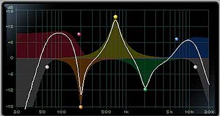
Equalization in sound recording and reproduction is the process of adjusting the volume of different frequency bands within an audio signal. The circuit or equipment used to achieve this is called an equalizer.


