AM was the earliest modulation method used for transmitting audio in radio broadcasting. It was developed during the first quarter of the 20th century beginning with Roberto Landell de Moura and Reginald Fessenden's radiotelephone experiments in 1900.[2] This original form of AM is sometimes called double-sideband amplitude modulation (DSBAM), because the standard method produces sidebands on either side of the carrier frequency. Single-sideband modulation uses bandpass filters to eliminate one of the sidebands and possibly the carrier signal, which improves the ratio of message power to total transmission power, reduces power handling requirements of line repeaters, and permits better bandwidth utilization of the transmission medium.
In electronics and telecommunications, modulation is the variation of a property of a continuous wavecarrier signal according to an information-bearing signal, such as an audio signal which represents sound, or a video signal which represents images. In this sense, the carrier wave, which has a much higher frequency than the message signal, carries the information. At the receiving station, the message signal is extracted from the modulated carrier by demodulation.
In general form, a modulation process of a sinusoidal carrier wave may be described by the following equation:[3]
.
A(t) represents the time-varying amplitude of the sinusoidal carrier wave and the cosine-term is the carrier at its angular frequency, and the instantaneous phase deviation . This description directly provides the two major groups of modulation, amplitude modulation and angle modulation. In angle modulation, the term A(t) is constant and the second term of the equation has a functional relationship to the modulating message signal. Angle modulation provides two methods of modulation, frequency modulation and phase modulation.[4]:27–28
In amplitude modulation, the angle term is held constant and the first term, A(t), of the equation has a functional relationship to the modulating message signal.
The modulating message signal may be analog in nature, or it may be a digital signal, in which case the technique is generally called amplitude-shift keying.[5]:124–128
For example, in AM radio communication, a continuous wave radio-frequency signal has its amplitude modulated by an audio waveform before transmission. The message signal determines the envelope of the transmitted waveform. In the frequency domain, amplitude modulation produces a signal with power concentrated at the carrier frequency and two adjacent sidebands. Each sideband is equal in bandwidth to that of the modulating signal, and is a mirror image of the other. Standard AM is thus sometimes called "double-sideband amplitude modulation" (DSBAM).
A disadvantage of all amplitude modulation techniques, not only standard AM, is that the receiver amplifies and detects noise and electromagnetic interference in equal proportion to the signal. Increasing the received signal-to-noise ratio, say, by a factor of 10 (a 10 decibel improvement), thus would require increasing the transmitter power by a factor of 10. This is in contrast to frequency modulation (FM) and digital radio where the effect of such noise following demodulation is strongly reduced so long as the received signal is well above the threshold for reception. For this reason AM broadcast is not favored for music and high fidelity broadcasting, but rather for voice communications and broadcasts (sports, news, talk radio etc.).
AM is inefficient in power usage, as at least two-thirds of the transmitting power is concentrated in the carrier signal. The carrier signal contains none of the transmitted information (voice, video, data, etc.). Its presence provides a simple means of demodulation using envelope detection, providing a frequency and phase reference for extracting the message signal from the sidebands. In some modulation systems based on AM, a lower transmitter power is required through partial or total elimination of the carrier component, however receivers for these signals are more complex because they must provide a precise carrier frequency reference signal (usually as shifted to the intermediate frequency) from a greatly reduced "pilot" carrier (in reduced-carrier transmission or DSB-RC) to use in the demodulation process. Even with the carrier eliminated in double-sideband suppressed-carrier transmission, carrier regeneration is possible using a Costas phase-locked loop.[6]
This does not work for single-sideband suppressed-carrier transmission (SSB-SC), leading to the characteristic "Donald Duck" sound from such receivers when slightly detuned. Single-sideband AM is nevertheless used widely in amateur radio and other voice communications because it has power and bandwidth efficiency (cutting the RF bandwidth in half compared to standard AM). On the other hand, in medium wave and short wave broadcasting, standard AM with the full carrier allows for reception using inexpensive receivers. The broadcaster absorbs the extra power cost to greatly increase potential audience.
Shift keying
A simple form of digital amplitude modulation which can be used for transmitting binary data is on–off keying, the simplest form of amplitude-shift keying, in which ones and zeros are represented by the presence or absence of a carrier. On–off keying is likewise used by radio amateurs to transmit Morse code where it is known as continuous wave (CW) operation, even though the transmission is not strictly "continuous". A more complex form of AM, quadrature amplitude modulation is now more commonly used with digital data, while making more efficient use of the available bandwidth.[7]
Analog telephony
A simple form of amplitude modulation is the transmission of speech signals from a traditional analog telephone set using a common battery local loop.[8] The direct current provided by the central office battery is a carrier with a frequency of 0Hz. It is modulated by a microphone (transmitter) in the telephone set according to the acoustic signal from the speaker. The result is a varying amplitude direct current, whose AC-component is the speech signal extracted at the central office for transmission to another subscriber.
Amplitude reference
An additional function provided by the carrier in standard AM, but which is lost in either single or double-sideband suppressed-carrier transmission, is that it provides an amplitude reference. In the receiver, the automatic gain control (AGC) responds to the carrier so that the reproduced audio level stays in a fixed proportion to the original modulation. On the other hand, with suppressed-carrier transmissions there is no transmitted power during pauses in the modulation, so the AGC must respond to peaks of the transmitted power during peaks in the modulation. This typically involves a so-called fast attack, slow decay circuit which holds the AGC level for a second or more following such peaks, in between syllables or short pauses in the program. This is very acceptable for communications radios, where compression of the audio aids intelligibility. However, it is absolutely undesired for music or normal broadcast programming, where a faithful reproduction of the original program, including its varying modulation levels, is expected.
One of the crude pre-vacuum tube AM transmitters, a Telefunken arc transmitter from 1906. The carrier wave is generated by 6 electric arcs in the vertical tubes, connected to a tuned circuit. Modulation is done by the large carbon microphone (cone shape) in the antenna lead. One of the first vacuum tube AM radio transmitters, built by Meissner in 1913 with an early triode tube by Robert von Lieben. He used it in a historic 36km (22mi) voice transmission from Berlin to Nauen, Germany. Compare its small size with the arc transmitter above.
Amplitude modulation was used in experiments of multiplex telegraph and telephone transmission in the late 1800s.[9] However, the practical development of this technology is identified with the period between 1900 and 1920 of radiotelephone transmission, that is, the effort to send audio signals by radio waves. The first radio transmitters, called spark gap transmitters, transmitted information by wireless telegraphy, using pulses of the carrier wave to spell out text messages in Morse code. They could not transmit audio because the carrier consisted of strings of damped waves, pulses of radio waves that declined to zero, and sounded like a buzz in receivers. In effect they were already amplitude modulated.[10][11]
Continuous waves
The first AM transmission was made by Canadian-born American researcher Reginald Fessenden[12] on 23 December 1900[13] using a spark gap transmitter with a specially designed high frequency 10kHz interrupter,[14] over a distance of one mile (1.6km) at Cobb Island, Maryland, US. His first transmitted words were, "Hello. One, two, three, four. Is it snowing where you are, Mr. Thiessen?".[13] Though his words were "perfectly intelligible", the spark created a loud and unpleasant noise.[14]
Fessenden was a significant figure in the development of AM radio. He was one of the first researchers to realize, from experiments like the above, that the existing technology for producing radio waves, the spark transmitter, was not usable for amplitude modulation, and that a new kind of transmitter, one that produced sinusoidalcontinuous waves, was needed. This was a radical idea at the time, because experts believed the impulsive spark was necessary to produce radio frequency waves, and Fessenden was ridiculed. He invented and helped develop one of the first continuous wave transmitters – the Alexanderson alternator, with which he made what is considered the first AM public entertainment broadcast on Christmas Eve, 1906. He also discovered the principle on which AM is based, heterodyning, and invented one of the first detectors able to rectify and receive AM, the electrolytic detector or "liquid baretter", in 1902. Other radio detectors invented for wireless telegraphy, such as the Fleming valve (1904) and the crystal detector (1906) also proved able to rectify AM signals, so the technological hurdle was generating AM waves; receiving them was not a problem.[11]:36,55–75,195[10]:76–77,116–117,125,133–134,162
The modifications necessary to transmit AM were clumsy and resulted in very low quality audio. Modulation was usually accomplished by a carbon microphone inserted directly in the antenna or ground wire; its varying resistance varied the current to the antenna. The limited power handling ability of the microphone severely limited the power of the first radiotelephones; many of the microphones were water-cooled.[15]:1102
Vacuum tubes
The 1912 discovery of the amplifying ability of the Audion tube, invented in 1906 by Lee de Forest, solved these problems. The vacuum tube feedback oscillator, invented in 1912 by Edwin Armstrong and Alexander Meissner, was a cheap source of continuous waves and could be easily modulated to make an AM transmitter. Modulation did not have to be done at the output but could be applied to the signal before the final amplifier tube, so the microphone or other audio source didn't have to modulate a high-power radio signal. Wartime research greatly advanced the art of AM modulation, and after the war the availability of cheap tubes sparked a great increase in the number of radio stations experimenting with AM transmission of news or music. The vacuum tube was responsible for the rise of AM broadcasting around 1920, the first electronic mass communication medium. Amplitude modulation was virtually the only type used for radio broadcasting until FM broadcasting began after World War II.[11]:203–205,229–230,237–242[10]:174,177,235,355–357
At the same time as AM radio began, telephone companies such as AT&T were developing the other large application for AM: sending multiple telephone calls through a single wire by modulating them on separate carrier frequencies, called frequency division multiplexing.[9]
Single-sideband
In 1915, John Renshaw Carson formulated the first mathematical description of amplitude modulation, showing that a signal and carrier frequency combined in a nonlinear device creates a sideband on both sides of the carrier frequency. Passing the modulated signal through another nonlinear device can extract the original baseband signal.[9] His analysis also showed that only one sideband was necessary to transmit the audio signal, and Carson patented single-sideband modulation (SSB) on 1 December 1915.[9] This advanced variant of amplitude modulation was adopted by AT&T for longwave transatlantic telephone service beginning 7 January 1927. After WW-II, it was developed for military aircraft communication.
Analysis
Illustration of amplitude modulation
The carrier wave (sine wave) of frequency fc and amplitude A is expressed by
.
The message signal, such as an audio signal that is used for modulating the carrier, is m(t), and has a frequency fm, much lower than fc:
,
where m is the amplitude sensitivity, M is the amplitude of modulation. If m < 1, (1 + m(t)/A) is always positive for undermodulation. If m > 1 then overmodulation occurs and reconstruction of message signal from the transmitted signal would lead in loss of original signal. Amplitude modulation results when the carrier c(t) is multiplied by the positive quantity (1 + m(t)/A):
In this simple case m is identical to the modulation index, discussed below. With m = 0.5 the amplitude modulated signal y(t) thus corresponds to the top graph (labelled "50% Modulation") in figure 4.
Therefore, the modulated signal has three components: the carrier wave c(t) which is unchanged in frequency, and two sidebands with frequencies slightly above and below the carrier frequency fc.[4]
Spectrum
Figure 2: Double-sided spectra of baseband and AM signals.
A useful modulation signal m(t) is usually more complex than a single sine wave, as treated above. However, by the principle of Fourier decomposition, m(t) can be expressed as the sum of a set of sine waves of various frequencies, amplitudes, and phases. Carrying out the multiplication of 1 + m(t) with c(t) as above, the result consists of a sum of sine waves. Again, the carrier c(t) is present unchanged, but each frequency component of m at fi has two sidebands at frequencies fc + fi and fc – fi. The collection of the former frequencies above the carrier frequency is known as the upper sideband, and those below constitute the lower sideband. The modulation m(t) may be considered to consist of an equal mix of positive and negative frequency components, as shown in the top of figure 2. One can view the sidebands as that modulation m(t) having simply been shifted in frequency by fc as depicted at the bottom right of figure 2.[16]:75–76
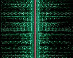
Figure 3: The spectrogram of an AM voice broadcast shows the two sidebands (green) on either side of the carrier (red) with time proceeding in the vertical direction.
The short-term spectrum of modulation, changing as it would for a human voice for instance, the frequency content (horizontal axis) may be plotted as a function of time (vertical axis), as in figure 3. It can again be seen that as the modulation frequency content varies, an upper sideband is generated according to those frequencies shifted above the carrier frequency, and the same content mirror-imaged in the lower sideband below the carrier frequency. At all times, the carrier itself remains constant, and of greater power than the total sideband power.
Power and spectrum efficiency
The RF bandwidth of an AM transmission (refer to figure 2, but only considering positive frequencies) is twice the bandwidth of the modulating (or "baseband") signal, since the upper and lower sidebands around the carrier frequency each have a bandwidth as wide as the highest modulating frequency. Although the bandwidth of an AM signal is narrower than one using frequency modulation (FM), it is twice as wide as single-sideband techniques; it thus may be viewed as spectrally inefficient. Within a frequency band, only half as many transmissions (or "channels") can thus be accommodated. For this reason analog television employs a variant of single-sideband (known as vestigial sideband, somewhat of a compromise in terms of bandwidth) in order to reduce the required channel spacing.[4]:175–176[5]
Another improvement over standard AM is obtained through reduction or suppression of the carrier component of the modulated spectrum. In figure 2 this is the spike in between the sidebands; even with full (100%) sine wave modulation, the power in the carrier component is twice that in the sidebands, yet it carries no unique information. Thus there is a great advantage in efficiency in reducing or totally suppressing the carrier, either in conjunction with elimination of one sideband (single-sideband suppressed-carrier transmission) or with both sidebands remaining (double sideband suppressed carrier). While these suppressed carrier transmissions are efficient in terms of transmitter power, they require more sophisticated receivers employing synchronous detection and regeneration of the carrier frequency. For that reason, standard AM continues to be widely used, especially in broadcast transmission, to allow for the use of inexpensive receivers using envelope detection. Even (analog) television, with a (largely) suppressed lower sideband, includes sufficient carrier power for use of envelope detection. But for communications systems where both transmitters and receivers can be optimized, suppression of both one sideband and the carrier represent a net advantage and are frequently employed.[6]
A technique used widely in broadcast AM transmitters is an application of the Hapburg carrier, first proposed in the 1930s but impractical with the technology then available. During periods of low modulation the carrier power would be reduced and would return to full power during periods of high modulation levels. This has the effect of reducing the overall power demand of the transmitter and is most effective on speech type programmes. Various trade names are used for its implementation by the transmitter manufacturers from the late 80's onwards.
Modulation index
The AM modulation index is a measure based on the ratio of the modulation excursions of the RF signal to the level of the unmodulated carrier. It is thus defined as:
where and are the modulation amplitude and carrier amplitude, respectively; the modulation amplitude is the peak (positive or negative) change in the RF amplitude from its unmodulated value. Modulation index is normally expressed as a percentage, and may be displayed on a meter connected to an AM transmitter.
So if , carrier amplitude varies by 50% above (and below) its unmodulated level, as is shown in the first waveform, below. For , it varies by 100% as shown in the illustration below it. With 100% modulation the wave amplitude sometimes reaches zero, and this represents full modulation using standard AM and is often a target (in order to obtain the highest possible signal-to-noise ratio) but mustn't be exceeded. Increasing the modulating signal beyond that point, known as overmodulation, causes a standard AM modulator (see below) to fail, as the negative excursions of the wave envelope cannot become less than zero, resulting in distortion ("clipping") of the received modulation. Transmitters typically incorporate a limiter circuit to avoid overmodulation, and/or a compressor circuit (especially for voice communications) in order to still approach 100% modulation for maximum intelligibility above the noise. Such circuits are sometimes referred to as a vogad.
However it is possible to talk about a modulation index exceeding 100%, without introducing distortion, in the case of double-sideband reduced-carrier transmission. In that case, negative excursions beyond zero entail a reversal of the carrier phase, as shown in the third waveform below. This cannot be produced using the efficient high-level (output stage) modulation techniques (see below) which are widely used especially in high power broadcast transmitters. Rather, a special modulator produces such a waveform at a low level followed by a linear amplifier. What's more, a standard AM receiver using an envelope detector is incapable of properly demodulating such a signal. Rather, synchronous detection is required.[6]
Thus double-sideband transmission is generally not referred to as "AM" even though it generates an identical RF waveform as standard AM as long as the modulation index is below 100%. Such systems more often attempt a radical reduction of the carrier level compared to the sidebands (where the useful information is present) to the point of double-sideband suppressed-carrier transmission where the carrier is (ideally) reduced to zero. In all such cases the term "modulation index" loses its value as it refers to the ratio of the modulation amplitude to a rather small (or zero) remaining carrier amplitude.
Figure 4: Modulation depth. In the diagram, the unmodulated carrier has an amplitude of 1.
Modulation methods
Anode (plate) modulation. A tetrode's plate and screen grid voltage is modulated via an audio transformer. The resistor R1 sets the grid bias; both the input and output are tuned circuits with inductive coupling.
Modulation circuit designs may be classified as low- or high-level (depending on whether they modulate in a low-power domain—followed by amplification for transmission—or in the high-power domain of the transmitted signal).[17]
Low-level generation
In modern radio systems, modulated signals are generated via digital signal processing (DSP). With DSP many types of AM are possible with software control (including DSB with carrier, SSB suppressed-carrier and independent sideband, or ISB). Calculated digital samples are converted to voltages with a digital-to-analog converter, typically at a frequency less than the desired RF-output frequency. The analog signal must then be shifted in frequency and linearly amplified to the desired frequency and power level (linear amplification must be used to prevent modulation distortion).[18] This low-level method for AM is used in many Amateur Radio transceivers.[19]
AM may also be generated at a low level, using analog methods described in the next section.
Older designs (for broadcast and amateur radio) also generate AM by controlling the gain of the transmitter's final amplifier (generally class-C, for efficiency), reflecting the strong emphasis on improving efficiency in early high-power transmitters. The following types are for vacuum tube transmitters, but similar options are available with transistors:[21][22]
Plate modulation
In plate modulation, the plate voltage of the RF amplifier is modulated with the audio signal. The audio power requirement is 50 percent of the RF-carrier power.[23]
RF amplifier plate voltage is fed through a choke (high-value inductor). The AM modulation tube plate is fed through the same inductor, so the modulator tube diverts current from the RF amplifier. The choke acts as a constant current source in the audio range. This system has a low power efficiency.[15]
Control grid modulation
The operating bias and gain of the final RF amplifier can be controlled by varying the voltage of the control grid. This method requires little audio power, but care must be taken to reduce distortion.[15]:1102[24]:32–38
Clamp tube (screen grid) modulation
The screen-grid bias may be controlled through a clamp tube, which reduces voltage according to the modulation signal. It is difficult to approach 100-percent modulation while maintaining low distortion with this system.[24]
A two-tube AM amplifier in which the first tube provides the power under carrier conditions, while a second operates only for positive modulation peaks. A quarter-wave impedance inverter between the two varies the load seen by the first tube over the modulation cycle. As originally described by Doherty, the system is not itself a modulator but a high-efficiency linear power amplifier that requires a pre-modulated RF signal to drive the grids. Overall efficiency is good, and distortion is low.[25][4]:150–151
Two tubes are operated in parallel, but partially out of phase with each other. As they are differentially phase modulated their combined amplitude is greater or smaller. Efficiency is good and distortion low when properly adjusted.[15]:1106
A highly efficient high voltage power supply is applied to the tube plate. The output voltage of this supply is varied at an audio rate to follow the program. This system was pioneered by Hilmer Swanson and has a number of variations, all of which achieve high efficiency and sound quality.[15]:1106–1109[26]
Digital methods
The Harris Corporation obtained a patent for synthesizing a modulated high-power carrier wave from a set of digitally selected low-power amplifiers, running in phase at the same carrier frequency.[27][28] The input signal is sampled by a conventional audio analog-to-digital converter (ADC), and fed to a digital exciter, which modulates overall transmitter output power by switching a series of low-power solid-state RF amplifiers on and off. The combined output drives the antenna system.
Demodulation methods
The simplest form of an AM demodulator consists of a diode configured as an envelope detector. As described by Frederick Terman in 1943, the diode rectifier was the most widely used detector for AM signals, providing a simple means of recovering the modulation envelope.[29] In 1904, John Ambrose Fleming developed such a circuit for a radio-wave detector in the crystal radio.[30] Adding variable capacitors to the crystal detector enables tuning to a specific frequency.[16]:104-106},111,115
Another type of demodulator, the product detector, can provide better-quality demodulation with additional circuit complexity.[4]:157–158
↑AT&T Bell Laboratories Staff (1984). R.J. Rey (ed.). Engineering and Operations in the Bell System (2ed.). Murray Hill, NJ: AT&T Bell Laboratories. p.211. ISBN0-932764-04-5.
123McNicol, Donald (1946). Radio's Conquest of Space: The Experimental Rise in Radio Communication. New York: Murray Hill Books, Inc. pp.66–68, 98–105.
123Aitken, Hugh (1985). The Continuous Wave: Technology and American Radio, 1900-1932. Princeton: Princeton University Press. p.30,54. ISBN0691023905.
12Advisory Group for Research and Development (AGARD) (2 October 1992). ELF/VLF/LF Radio Propagation and Systems Aspects(PDF) (Report). North Atlantic Treaty Organization (NATO). Retrieved 16 December 2024.
12345Welton, Jeff; Stanley, John (2018). Cavell, Garrison (ed.). Medium Wave (AM) Transmitters in National Association of Broadcasters Engineering Handbook, 11th Edition. New York: Routledge. pp.1102–1103. ISBN9781138930513.
12Nahin, Paul (2024). The Mathematical Radio: Inside the Magic of AM, FM, and Single-Sideband. Princeton: Princeton University Press. pp.74–76. ISBN9780691235318.
↑Silver, Ward, ed. (2011). "Ch. 15 DSP and Software Radio Design". The ARRL Handbook for Radio Communications (Eighty-eighthed.). American Radio Relay League. ISBN978-0-87259-096-0.
↑Silver, Ward, ed. (2011). "Ch. 14 Transceivers". The ARRL Handbook for Radio Communications (Eighty-eighthed.). American Radio Relay League. ISBN978-0-87259-096-0.
Newkirk, David and Karlquist, Rick (2004). Mixers, modulators and demodulators. In D. G. Reed (ed.), The ARRL Handbook for Radio Communications (81st ed.), pp.15.1–15.36. Newington: ARRL. ISBN0-87259-196-4.
This page is based on this Wikipedia article Text is available under the CC BY-SA 4.0 license; additional terms may apply. Images, videos and audio are available under their respective licenses.