Detector (radio)

Last updated

In radio, a detector is a device or circuit that extracts information from a modulated radio frequency current or voltage. The term dates from the first three decades of radio (1888-1918). Unlike modern radio stations which transmit sound (an audio signal) on an uninterrupted carrier wave, early radio stations transmitted information by radiotelegraphy . The transmitter was switched on and off to produce long or short periods of radio waves, spelling out text messages in Morse code. Therefore, early radio receivers did not have to demodulate the radio signal, but just distinguish between the presence or absence of a radio signal, to reproduce the Morse code "dots" and "dashes". The device that performed this function in the receiver circuit was called a detector. [1] A variety of different detector devices, such as the coherer, electrolytic detector, magnetic detector and the crystal detector, were used during the wireless telegraphy era until superseded by vacuum tube technology.

Contents

After the invention of amplitude modulation (AM) enabled the development of AM radiotelephony, the transmission of sound (audio), during World War 1, the term evolved to mean a demodulator, (usually a vacuum tube) which extracted the audio signal from the radio frequency carrier wave. This is its current meaning, although modern detectors usually consist of semiconductor diodes, transistors, or integrated circuits.

In a superheterodyne receiver the term is also sometimes used to refer to the mixer, the tube or transistor which converts the incoming radio frequency signal to the intermediate frequency. The mixer is called the first detector, while the demodulator that extracts the audio signal from the intermediate frequency is called the second detector. In microwave and millimeter wave technology the terms detector and crystal detector refer to waveguide or coaxial transmission line components, used for power or SWR measurement, that typically incorporate point contact diodes or surface barrier Schottky diodes.

A coherer detector, useful only for Morse code signals. Tapping coherer.jpg
A coherer detector, useful only for Morse code signals.

Amplitude modulation detectors

Envelope detector

A simple envelope detector Simple envelope detector.svg
A simple envelope detector
A simple crystal radio with no tuned circuit can be used to listen to strong AM broadcast signals Simplest crystal radio circuit.svg
A simple crystal radio with no tuned circuit can be used to listen to strong AM broadcast signals

One major technique is known as envelope detection. The simplest form of envelope detector is the diode detector that consists of a diode connected between the input and output of the circuit, with a resistor and capacitor in parallel from the output of the circuit to the ground to form a low pass filter. If the resistor and capacitor are correctly chosen, the output of this circuit will be a nearly identical voltage-shifted version of the original signal.

An early form of envelope detector was the crystal detector, which was used in the crystal set radio receiver. A later version using a crystal diode is still used in crystal radio sets today. The limited frequency response of the headset eliminates the RF component, making the low pass filter unnecessary.

More sophisticated envelope detectors include the grid-leak detector, the plate detector, the infinite-impedance detector, transistor equivalents of them and precision rectifiers using operational amplifiers.

Product detector

A product detector is a type of demodulator used for AM and SSB signals, where the original carrier signal is removed by multiplying the received signal with a signal at the carrier frequency (or near to it). Rather than converting the envelope of the signal into the decoded waveform by rectification as an envelope detector would, the product detector takes the product of the modulated signal and a local oscillator, hence the name. By heterodyning, the received signal is mixed (in some type of nonlinear device) with a signal from the local oscillator, to give sum and difference frequencies to the signals being mixed, just as a first mixer stage in a superhet would produce an intermediate frequency; the beat frequency in this case, the low frequency modulating signal is recovered and the unwanted high frequencies filtered out from the output of the product detector. Because the sidebands of an amplitude-modulated signal contain all the information in the carrier displaced from the center by a function of their frequency, a product detector simply mixes the sidebands down into the audible range so that the original audio may be heard.

Product detector circuits are essentially ring modulators or synchronous detectors and closely related to some phase-sensitive detector circuits. They can be implemented using something as simple as ring of diodes or a single dual-gate Field Effect Transistor to anything as sophisticated as an Integrated Circuit containing a Gilbert cell. Product detectors are typically preferred to envelope detectors by shortwave listeners and radio amateurs as they permit the reception of both AM and SSB signals. They may also demodulate CW transmissions if the beat frequency oscillator is tuned slightly above or below the carrier.

Frequency and phase modulation detectors

AM detectors cannot demodulate FM and PM signals because both have a constant amplitude. However an AM radio may detect the sound of an FM broadcast by the phenomenon of slope detection which occurs when the radio is tuned slightly above or below the nominal broadcast frequency. Frequency variation on one sloping side of the radio tuning curve gives the amplified signal a corresponding local amplitude variation, to which the AM detector is sensitive. Slope detection gives inferior distortion and noise rejection compared to the following dedicated FM detectors that are normally used.

Phase detector

A phase detector is a nonlinear [ disambiguation needed ] device whose output represents the phase difference between the two oscillating input signals. It has two inputs and one output: a reference signal is applied to one input and the phase or frequency modulated signal is applied to the other. The output is a signal that is proportional to the phase difference between the two inputs.

In phase demodulation the information is contained in the amount and rate of phase shift in the carrier wave.

The Foster–Seeley discriminator

The Foster–Seeley discriminator [2] [3] is a widely used FM detector. The detector consists of a special center-tapped transformer feeding two diodes in a full wave DC rectifier circuit. When the input transformer is tuned to the signal frequency, the output of the discriminator is zero. When there is no deviation of the carrier, both halves of the center tapped transformer are balanced. As the FM signal swings in frequency above and below the carrier frequency, the balance between the two halves of the center-tapped secondary is destroyed and there is an output voltage proportional to the frequency deviation.

Ratio detector

A ratio detector using solid-state diodes Ratio detector.svg
A ratio detector using solid-state diodes

The ratio detector [4] [5] [6] [7] is a variant of the Foster–Seeley discriminator, but one diode conducts in an opposite direction, and using a tertiary winding in the preceding transformer. The output in this case is taken between the sum of the diode voltages and the center tap. The output across the diodes is connected to a large value capacitor, which eliminates AM noise in the ratio detector output. The ratio detector has the advantage over the Foster–Seeley discriminator that it will not respond to AM signals, thus potentially saving a limiter stage; however the output is only 50% of the output of a discriminator for the same input signal. The ratio detector has wider bandwidth but more distortion than the Foster–Seeley discriminator.

Quadrature detector

In quadrature detectors, the received FM signal is split into two signals. One of the two signals is then passed through a high-reactance capacitor, which shifts the phase of that signal by 90 degrees. This phase-shifted signal is then applied to an LC circuit, which is resonant at the FM signal's unmodulated, "center," or "carrier" frequency. If the received FM signal's frequency equals the center frequency, then the two signals will have a 90-degree phase difference and they are said to be in "phase quadrature" — hence the name of this method. The two signals are then multiplied together in an analog or digital device, which serves as a phase detector; that is, a device whose output is proportional to the phase difference between two signals. In the case of an unmodulated FM signal, the phase detector's output is — after the output has been filtered; that is, averaged over time — constant; namely, zero. However, if the received FM signal has been modulated, then its frequency will vary from the center frequency. In this case, the resonant LC circuit will further shift the phase of the signal from the capacitor, so that the signal's total phase shift will be the sum of the 90 degrees imposed by the capacitor, and the positive or negative phase change imposed by the LC circuit. Now the output from the phase detector will differ from zero, and in this way, one recovers the original signal that was used to modulate the FM carrier.

XOR gate detector

The detection process described above can also be accomplished by combining, in an exclusive-OR (XOR) logic gate, the limited original FM signal and either a copy of that signal passed through a network which imposes a phase shift that varies with frequency, e.g. an LC circuit (and then limited as well), or a fixed-frequency square wave carrier at the center frequency of the signal. The XOR gate produces a stream of output pulses the duty cycle of which corresponds to the phase difference between the two signals. Due to the varying phase difference between the two inputs, a pulse-width modulated (PWM) signal is produced. When a low-pass filter is applied to those pulses, the filter's output rises as the pulses grow longer and its output falls as the pulses grow shorter. In this way, one recovers the original signal that was used to modulate the FM carrier.

When a phase-shifted version of the original signal is used, the result is a frequency demodulation, as the frequency difference between the inputs of the XOR gate remains zero and thus does not affect their phase relationship.

With a fixed-frequency carrier, the result is a phase demodulation, which, in this case is an integral of the original modulating signal.

Other FM detectors

Less common, specialized, or obsolescent types of detectors include: [8]

Phase-locked loop detector

The phase-locked loop detector requires no frequency-selective LC network to accomplish demodulation. In this system, a voltage controlled oscillator (VCO) is phase locked by a feedback loop, which forces the VCO to follow the frequency variations of the incoming FM signal. The low-frequency error voltage that forces the VCO's frequency to track the frequency of the modulated FM signal is the demodulated audio output. The phase-locked loop detector should not be confused with the phase-locked loop frequency synthesizer, which is often used in digitally-tuned AM and FM radios to generate the local oscillator frequency.

See also

Related Research Articles

<span class="mw-page-title-main">Amplitude modulation</span> Radio modulation via wave amplitude

Amplitude modulation (AM) is a modulation technique used in electronic communication, most commonly for transmitting messages with a radio wave. In amplitude modulation, the amplitude of the wave is varied in proportion to that of the message signal, such as an audio signal. This technique contrasts with angle modulation, in which either the frequency of the carrier wave is varied, as in frequency modulation, or its phase, as in phase modulation.

<span class="mw-page-title-main">Superheterodyne receiver</span> Type of radio receiver

A superheterodyne receiver, often shortened to superhet, is a type of radio receiver that uses frequency mixing to convert a received signal to a fixed intermediate frequency (IF) which can be more conveniently processed than the original carrier frequency. It was invented by French radio engineer and radio manufacturer Lucien Lévy. Virtually all modern radio receivers use the superheterodyne principle.

A phase-locked loop or phase lock loop (PLL) is a control system that generates an output signal whose phase is fixed relative to the phase of an input signal. Keeping the input and output phase in lockstep also implies keeping the input and output frequencies the same, thus a phase-locked loop can also track an input frequency. And by incorporating a frequency divider, a PLL can generate a stable frequency that is a multiple of the input frequency.

Demodulation is extracting the original information-bearing signal from a carrier wave. A demodulator is an electronic circuit that is used to recover the information content from the modulated carrier wave. There are many types of modulation so there are many types of demodulators. The signal output from a demodulator may represent sound, images or binary data.

<span class="mw-page-title-main">Ring modulation</span> Frequency mixing function in signal processing

In electronics, ring modulation is a signal processing function, an implementation of frequency mixing, in which two signals are combined to yield an output signal. One signal, called the carrier, is typically a sine wave or another simple waveform; the other signal is typically more complicated and is called the input or the modulator signal. A ring modulator is an electronic device for ring modulation. A ring modulator may be used in music synthesizers and as an effects unit.

A product detector is a type of demodulator used for AM and SSB signals. Rather than converting the envelope of the signal into the decoded waveform like an envelope detector, the product detector takes the product of the modulated signal and a local oscillator, hence the name. A product detector is a frequency mixer.

<span class="mw-page-title-main">Envelope detector</span> Electronic circuit

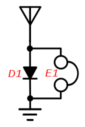
An envelope detector is an electronic circuit that takes a (relatively) high-frequency amplitude modulated signal as input and provides an output, which is the demodulated envelope of the original signal.

<span class="mw-page-title-main">Phase detector</span> Electrical circuit detecting phase difference

A phase detector or phase comparator is a frequency mixer, analog multiplier or logic circuit that generates a signal which represents the difference in phase between two signal inputs.

A variable frequency oscillator (VFO) in electronics is an oscillator whose frequency can be tuned over some range. It is a necessary component in any tunable radio transmitter and in receivers that works by the superheterodyne principle. The oscillator controls the frequency to which the apparatus is tuned.

<span class="mw-page-title-main">Radio receiver</span> Device for receiving radio broadcasts

In radio communications, a radio receiver, also known as a receiver, a wireless, or simply a radio, is an electronic device that receives radio waves and converts the information carried by them to a usable form. It is used with an antenna. The antenna intercepts radio waves and converts them to tiny alternating currents which are applied to the receiver, and the receiver extracts the desired information. The receiver uses electronic filters to separate the desired radio frequency signal from all the other signals picked up by the antenna, an electronic amplifier to increase the power of the signal for further processing, and finally recovers the desired information through demodulation.

<span class="mw-page-title-main">Foster–Seeley discriminator</span>

The Foster–Seeley discriminator is a common type of FM detector circuit, invented in 1936 by Dudley E. Foster and Stuart William Seeley. The Foster–Seeley discriminator was envisioned for automatic frequency control of receivers, but also found application in demodulating an FM signal.

<span class="mw-page-title-main">Beat frequency oscillator</span>

In a radio receiver, a beat frequency oscillator or BFO is a dedicated oscillator used to create an audio frequency signal from Morse code radiotelegraphy (CW) transmissions to make them audible. The signal from the BFO is mixed with the received signal to create a heterodyne or beat frequency which is heard as a tone in the speaker. BFOs are also used to demodulate single-sideband (SSB) signals, making them intelligible, by essentially restoring the carrier that was suppressed at the transmitter. BFOs are sometimes included in communications receivers designed for short wave listeners; they are almost always found in communication receivers for amateur radio, which often receive CW and SSB signals.

<span class="mw-page-title-main">Voltage-controlled oscillator</span> Oscillator with frequency controlled by a voltage input

A voltage-controlled oscillator (VCO) is an electronic oscillator whose oscillation frequency is controlled by a voltage input. The applied input voltage determines the instantaneous oscillation frequency. Consequently, a VCO can be used for frequency modulation (FM) or phase modulation (PM) by applying a modulating signal to the control input. A VCO is also an integral part of a phase-locked loop. VCOs are used in synthesizers to generate a waveform whose pitch can be adjusted by a voltage determined by a musical keyboard or other input.

<span class="mw-page-title-main">Tuner (radio)</span> Frequency selection subsystem for various receiver systems

A tuner is a subsystem that receives radio frequency (RF) transmissions, such as FM broadcasting, and converts the selected carrier frequency and its associated bandwidth into a fixed frequency that is suitable for further processing, usually because a lower frequency is used on the output. Broadcast FM/AM transmissions usually feed this intermediate frequency (IF) directly into a demodulator that converts the radio signal into audio-frequency signals that can be fed into an amplifier to drive a loudspeaker.

<span class="mw-page-title-main">Grid-leak detector</span>

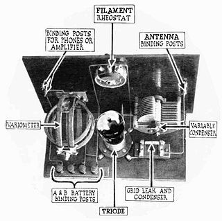
A grid leak detector is an electronic circuit that demodulates an amplitude modulated alternating current and amplifies the recovered modulating voltage. The circuit utilizes the non-linear cathode to control grid conduction characteristic and the amplification factor of a vacuum tube. Invented by Lee De Forest around 1912, it was used as the detector (demodulator) in the first vacuum tube radio receivers until the 1930s.

A direct-conversion receiver (DCR), also known as homodyne, synchrodyne, or zero-IF receiver, is a radio receiver design that demodulates the incoming radio signal using synchronous detection driven by a local oscillator whose frequency is identical to, or very close to the carrier frequency of the intended signal. This is in contrast to the standard superheterodyne receiver where this is accomplished only after an initial conversion to an intermediate frequency.

A radio transmitter or just transmitter is an electronic device which produces radio waves with an antenna. Radio waves are electromagnetic waves with frequencies between about 30 Hz and 300 GHz. The transmitter itself generates a radio frequency alternating current, which is applied to the antenna. When excited by this alternating current, the antenna radiates radio waves. Transmitters are necessary parts of all systems that use radio: radio and television broadcasting, cell phones, wireless networks, radar, two way radios like walkie talkies, radio navigation systems like GPS, remote entry systems, among numerous other uses.

<span class="mw-page-title-main">Plate detector (radio)</span>

In electronics, a plate detector is a vacuum tube circuit in which an amplifying tube having a control grid is operated in a non-linear region of its grid voltage versus plate current transfer characteristic, usually near plate current cutoff, to demodulate amplitude modulated carrier signal. This differs from the grid leak detector, which utilizes the non-linearity of the grid voltage versus grid current characteristic for demodulation. It also differs from the diode detector, which is a two-terminal device.

<span class="mw-page-title-main">Ratio detector</span>

The ratio detector is a type of detector circuit, commonly used in radio receivers for demodulating frequency modulated (FM) signal.

<span class="mw-page-title-main">Audion receiver</span>

An audion receiver makes use of a single vacuum tube or transistor to detect and amplify signals. It is so called because it originally used the audion tube as the active element. Unlike a crystal detector or Fleming valve detector, the audion provided amplification of the signal as well as detection. The audion was invented by Lee De Forest.

References

  1. J. A. Fleming, The Principles of Electric Wave Telegraphy and Telephony, London: Longmans, Green & Co., 1919, p. 364
  2. US 2121103, Seeley, Stuart W.,"Frequency Variation Response Circuits",issued June 21, 1938
  3. Foster, D. E.; Seeley, S. W. (March 1937), "Automatic tuning, simplified circuits, and design practice", Proceedings of the Institute of Radio Engineers, 25 (3): 289–313, doi:10.1109/jrproc.1937.228940, S2CID   51654596 , part 1.
  4. US 2497840, Seeley, Stuart William,"Angle Modulation Detector",issued February 14, 1950
  5. US 2561089,Anderson, Earl I.,issued July 17, 1951
  6. Report L.B.-645: "Ratio detectors for FM receivers" (15 September 1945) issued by the Radio Corporation of America, RCA Laboratories Industry Service Division, 711 Fifth Avenue, N.Y., N.Y. Reprinted in Radio, pages 18-20 (October 1945).
  7. Seeley, Stuart W.; Avins, Jack (June 1947), "The ratio detector", RCA Review, 8 (2): 201–236
  8. D. S. Evans and G. R. Jessup, VHF-UHF Manual (3rd Edition), Radio Society of Great Britain, London, 1976 pages 4-48 through 4-51
  9. Charles Travis, "Automatic oscillator frequency control system" U.S. patent: 2,294,100 (filed: 4 February 1935; issued: August 1942). See also: Charles Travis, "Automatic frequency control," Proceedings of the Institute of Radio Engineers, vol. 23, no. 10, pages 1125-1141 (October 1935).