A rectifier is an electrical device that converts alternating current (AC), which periodically reverses direction, to direct current (DC), which flows in only one direction.
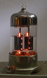
A tetrode is a vacuum tube having four active electrodes. The four electrodes in order from the centre are: a thermionic cathode, first and second grids and a plate. There are several varieties of tetrodes, the most common being the screen-grid tube and the beam tetrode. In screen-grid tubes and beam tetrodes, the first grid is the control grid and the second grid is the screen grid. In other tetrodes one of the grids is a control grid, while the other may have a variety of functions.

The Audion was an electronic detecting or amplifying vacuum tube invented by American electrical engineer Lee de Forest in 1906. It was the first triode, consisting of an evacuated glass tube containing three electrodes: a heated filament, a grid, and a plate. It is important in the history of technology because it was the first widely used electronic device which could amplify; a small electrical signal applied to the grid could control a larger current flowing from the filament to plate.

A regenerative circuit is an amplifier circuit that employs positive feedback. Some of the output of the amplifying device is applied back to its input so as to add to the input signal, increasing the amplification. One example is the Schmitt trigger, but the most common use of the term is in RF amplifiers, and especially regenerative receivers, to greatly increase the gain of a single amplifier stage.

In radio communications, a radio receiver, also known as a receiver, wireless or simply radio is an electronic device that receives radio waves and converts the information carried by them to a usable form. It is used with an antenna. The antenna intercepts radio waves and converts them to tiny alternating currents which are applied to the receiver, and the receiver extracts the desired information. The receiver uses electronic filters to separate the desired radio frequency signal from all the other signals picked up by the antenna, an electronic amplifier to increase the power of the signal for further processing, and finally recovers the desired information through demodulation.

In electronics, the dynatron oscillator, invented in 1918 by Albert Hull at General Electric, is an obsolete vacuum tube electronic oscillator circuit which uses a negative resistance characteristic in early tetrode vacuum tubes, caused by a process called secondary emission. It was the first negative resistance vacuum tube oscillator. The dynatron oscillator circuit was used to a limited extent as beat frequency oscillators (BFOs), and local oscillators in vacuum tube radio receivers as well as in scientific and test equipment from the 1920s to the 1940s but became obsolete around World War 2 due to the variability of secondary emission in tubes.

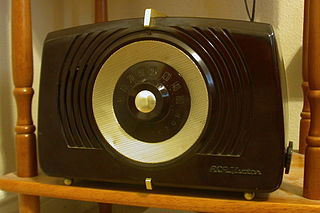
The term All American Five is a colloquial name for mass-produced, superheterodyne radio receivers that used five vacuum tubes in their design. These radio sets were designed to receive amplitude modulation (AM) broadcasts in the medium wave band, and were manufactured in the United States from the mid-1930s until the early 1960s. By eliminating a power transformer, cost of the units was kept low; the same principle was later applied to television receivers. Variations in the design for lower cost, shortwave bands, better performance or special power supplies existed, although many sets used an identical set of vacuum tubes.

A pentode is an electronic device having five active electrodes. The term most commonly applies to a three-grid amplifying vacuum tube, which was invented by Gilles Holst and Bernhard D.H. Tellegen in 1926. The pentode consists of an evacuated glass envelope containing five electrodes in this order: a cathode heated by a filament, a control grid, a screen grid, a suppressor grid, and a plate (anode). The pentode was developed from the tetrode tube by the addition of a third grid, the suppressor grid. This served to prevent secondary emission electrons emitted by the plate from reaching the screen grid, which caused instability and parasitic oscillations in the tetrode. The pentode is closely related to the beam tetrode. Pentodes were widely used in industrial and consumer electronic equipment such as radios and televisions until the 1960s, when they were replaced by transistors. Their main use now is in high power industrial applications such as radio transmitters. The obsolete consumer tubes are still used in a few legacy and specialty vacuum tube audio devices.
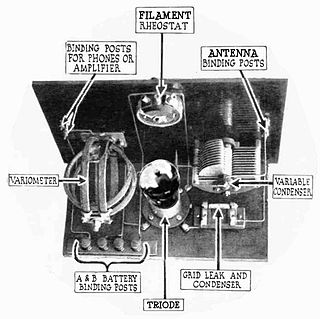
A grid leak detector is an electronic circuit that demodulates an amplitude modulated alternating current and amplifies the recovered modulating voltage. The circuit utilizes the non-linear cathode to control grid conduction characteristic and the amplification factor of a vacuum tube. Invented by Lee De Forest around 1912, it was used as the detector (demodulator) in the first vacuum tube radio receivers until the 1930s.

In the early days of electronics, vacuum tube devices were powered by batteries. Each battery had a different designation depending on which vacuum tube element it was associated with.
Biasing in electronics means establishing predetermined voltages or currents at various points of an electronic circuit for the purpose of establishing proper operating conditions in electronic components. Many electronic devices such as diodes, transistors and vacuum tubes, whose function is processing time-varying (AC) signals also require a steady (DC) current or voltage to operate correctly — a bias. The AC signal applied to them is superposed on this DC bias current or voltage. The operating point of a device, also known as bias point, quiescent point, or Q-point, is the DC voltage or current at a specified terminal of an active device with no input signal applied. A bias circuit is a portion of the device's circuit which supplies this steady current or voltage.
In electronics, cathode bias is a technique used with vacuum tubes to make the direct current (dc) cathode voltage positive in relation to the negative side of the plate voltage supply by an amount equal to the magnitude of the desired grid bias voltage.

The Fleming valve, also called the Fleming oscillation valve, was a thermionic valve or vacuum tube invented in 1904 by Englishman John Ambrose Fleming as a detector for early radio receivers used in electromagnetic wireless telegraphy. It was the first practical vacuum tube and the first thermionic diode, a vacuum tube whose purpose is to conduct current in one direction and block current flowing in the opposite direction. The thermionic diode was later widely used as a rectifier — a device which converts alternating current (AC) into direct current (DC) — in the power supplies of a wide range of electronic devices, until beginning to be replaced by the selenium rectifier in the early 1930s and almost completely replaced by the semiconductor diode in the 1960s. The Fleming valve was the forerunner of all vacuum tubes, which dominated electronics for 50 years. The IEEE has described it as "one of the most important developments in the history of electronics", and it is on the List of IEEE Milestones for electrical engineering.
A magic eye tube or tuning indicator, in technical literature called an electron-ray indicator tube, is a vacuum tube which gives a visual indication of the amplitude of an electronic signal, such as an audio output, radio-frequency signal strength, or other functions. The magic eye is a specific type of such a tube with a circular display similar to the EM34 illustrated. Its first broad application was as a tuning indicator in radio receivers, to give an indication of the relative strength of the received radio signal, to show when a radio station was properly tuned in.
An AC/DC receiver design is a style of power supply of vacuum tube radio or television receivers that eliminated the bulky and expensive mains transformer. A side-effect of the design was that the receiver could in principle operate from a DC supply as well as an AC supply. Consequently, they were known as "AC/DC receivers".

In electronics, a plate detector is a vacuum tube circuit in which an amplifying tube having a control grid is operated in a non-linear region of its grid voltage versus plate current transfer characteristic near plate current cutoff in order to demodulate an amplitude modulated carrier signal. This differs from the grid leak detector, which utilizes non-linearity of the grid voltage versus grid current characteristic for demodulation. It also differs from the diode detector, which is a two terminal device.
In vacuum tube technology, HT or high tension describes the main power supply to the circuit, which produces the current between anode and cathode. It is also known as the plate supply or voltage, B battery supply, or simply labeled ->B on circuit diagrams, from the days of battery powered circuitry.