Linear pulse-code modulation (LPCM) is a specific type of PCM in which the quantization levels are linearly uniform.[5] This is in contrast to PCM encodings in which quantization levels vary as a function of amplitude (as with the A-law algorithm or the μ-law algorithm). Though PCM is a more general term, it is often used to describe data encoded as LPCM.
A PCM stream has two basic properties that determine the stream's fidelity to the original analog signal: the sampling rate, which is the number of times per second that samples are taken; and the bit depth, which determines the number of possible digital values that can be used to represent each sample.
History
Early electrical communications started to sample signals in order to multiplex samples from multiple telegraphy sources and to convey them over a single telegraph cable. The American inventor Moses G. Farmer conceived telegraph time-division multiplexing (TDM) as early as 1853. Electrical engineer W. M. Miner, in 1903, used an electro-mechanical commutator for time-division multiplexing multiple telegraph signals; he also applied this technology to telephony. He obtained intelligible speech from channels sampled at a rate above 3500–4300Hz; lower rates proved unsatisfactory.
British engineer Alec Reeves, unaware of previous work, conceived the use of PCM for voice communication in 1937 while working for International Telephone and Telegraph in France. He described the theory and its advantages, but no practical application resulted. Reeves filed for a French patent in 1938, and his US patent was granted in 1943.[13] By this time Reeves had started working at the Telecommunications Research Establishment.[12]
The first transmission of speech by digital techniques, the SIGSALY encryption equipment, conveyed high-level Allied communications during World War II. In 1949, for the Canadian Navy's DATAR system, Ferranti Canada built a working PCM radio system that was able to transmit digitized radar data over long distances.[14]
PCM in the late 1940s and early 1950s used a cathode-raycoding tube with a plate electrode having encoding perforations.[15] As in an oscilloscope, the beam was swept horizontally at the sample rate while the vertical deflection was controlled by the input analog signal, causing the beam to pass through higher or lower portions of the perforated plate. The plate collected or passed the beam, producing current variations in binary code, one bit at a time. Rather than natural binary, the grid of Goodall's later tube was perforated to produce a glitch-free Gray code and produced all bits simultaneously by using a fan beam instead of a scanning beam.[16]
The T-carrier system, introduced in 1961, uses two twisted-pair transmission lines to carry 24 PCM telephone calls sampled at 8kHz and 8-bit resolution. This development improved capacity and call quality compared to the previous frequency-division multiplexing schemes.
In 1967, the first PCM recorder was developed by NHK's research facilities in Japan.[22] The 30kHz 12-bit device used a compander (similar to DBX Noise Reduction) to extend the dynamic range, and stored the signals on a video tape recorder. In 1969, NHK expanded the system's capabilities to 2-channel stereo and 32kHz 13-bit resolution. In January 1971, using NHK's PCM recording system, engineers at Denon recorded the first commercial digital recordings.[note 1][22]
In 1972, Denon unveiled the first 8-channel digital recorder, the DN-023R, which used a 4-head open reel broadcast video tape recorder to record in 47.25kHz, 13-bit PCM audio.[note 2] In 1977, Denon developed the portable PCM recording system, the DN-034R. Like the DN-023R, it recorded 8 channels at 47.25kHz, but it used 14-bits "with emphasis, making it equivalent to 15.5 bits."[22]
In 1979, the first digital pop album, Bop till You Drop, was recorded. It was recorded in 50kHz, 16-bit linear PCM using a 3M digital tape recorder.[23]
The compact disc (CD) brought PCM to consumer audio applications with its introduction in 1982. The CD uses a 44,100 Hz sampling frequency and 16-bit resolution and stores up to 80 minutes of stereo audio per disc.
PCM is the method of encoding typically used for uncompressed digital audio.[note 3]
The 4ESS switch introduced time-division switching into the US telephone system in 1976, based on medium scale integrated circuit technology.[26]
LPCM is used for the lossless encoding of audio data in the compact disc Red Book standard (informally also known as Audio CD), introduced in 1982.
AES3 (specified in 1985, upon which S/PDIF is based) is a particular format using LPCM.
LaserDiscs with digital sound have an LPCM track on the digital channel.
On PCs, PCM and LPCM often refer to the format used in WAV (defined in 1991) and AIFF audio container formats (defined in 1988). LPCM data may also be stored in other formats such as AU, raw audio format (header-less file) and various multimedia container formats.
LPCM has been defined as a part of the DVD (since 1995) and Blu-ray (since 2006) standards.[27][28][29] It is also defined as a part of various digital video and audio storage formats (e.g. DV since 1995,[30]AVCHD since 2006[31]).
LPCM is used by HDMI (defined in 2002), a single-cable digital audio/video connector interface for transmitting uncompressed digital data.
RF64 container format (defined in 2007) uses LPCM and also allows non-PCM bitstream storage: various compression formats contained in the RF64 file as data bursts (Dolby E, Dolby AC3, DTS, MPEG-1/MPEG-2 Audio) can be "disguised" as PCM linear.[32]
Modulation
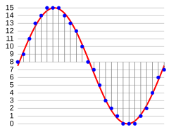
Sampling and quantization of a signal (red) for 4-bit LPCM over a time domain at specific frequency
In the diagram, a sine wave (red curve) is sampled and quantized for PCM. The sine wave is sampled at regular intervals, shown as vertical lines. For each sample, one of the available values (on the y-axis) is chosen. The PCM process is commonly implemented on a single integrated circuit called an analog-to-digital converter (ADC). This produces a fully discrete representation of the input signal (blue points) that can be easily encoded as digital data for storage or manipulation. Several PCM streams could also be multiplexed into a larger aggregate data stream, generally for transmission of multiple streams over a single physical link. One technique is called time-division multiplexing (TDM) and is widely used, notably in the modern public telephone system.
Demodulation
The electronics involved in producing an accurate analog signal from the discrete data are similar to those used for generating the digital signal. These devices are digital-to-analog converters (DACs). They produce a voltage or current (depending on type) that represents the value presented on their digital inputs. This output would then generally be filtered and amplified for use.
To recover the original signal from the sampled data, a demodulator can apply the procedure of modulation in reverse. After each sampling period, the demodulator reads the next value and transitions the output signal to the new value. As a result of these transitions, the signal retains a significant amount of high-frequency energy due to imaging effects. To remove these undesirable frequencies, the demodulator passes the signal through a reconstruction filter that suppresses energy outside the expected frequency range (greater than the Nyquist frequency).[note 4]
Standard sampling precision and rates
Common sample depths for LPCM are 8, 16, 20 or 24 bits per sample.[1][2][3][33]
LPCM encodes a single sound channel. Support for multichannel audio depends on file format and relies on synchronization of multiple LPCM streams.[5][34] While two channels (stereo) is the most common format, systems can support up to 8 audio channels (7.1 surround)[2][3] or more.
Common sampling frequencies are 48 kHz as used with DVD format videos, or 44.1kHz as used in CDs. Sampling frequencies of 96kHz or 192kHz can be used on some equipment, but the benefits have been debated.[35]
Limitations
The Nyquist–Shannon sampling theorem shows PCM devices can operate without introducing distortions within their designed frequency bands if they provide a sampling frequency at least twice that of the highest frequency contained in the input signal. For example, in telephony, the usable voice frequency band ranges from approximately 300 to 3400Hz.[36] For effective reconstruction of the voice signal, telephony applications therefore typically use an 8000Hz sampling frequency which is more than twice the highest usable voice frequency.
Regardless, there are potential sources of impairment implicit in any PCM system:
Choosing a discrete value that is near but not exactly at the analog signal level for each sample leads to quantization error. When dithering is used to compensate for this, it introduces additional noise.[note 5]
Between samples no measurement of the signal is made; the sampling theorem guarantees non-ambiguous representation and recovery of the signal only if it has no energy at frequency fs/2 or higher (one half the sampling frequency, known as the Nyquist frequency); higher frequencies will not be correctly represented or recovered and add aliasing distortion to the signal below the Nyquist frequency.
As samples are dependent on time, an accurate clock is required for accurate reproduction. If either the encoding or decoding clock is not stable, these imperfections will directly affect the output quality of the device.[note 6]
Processing and coding
Some forms of PCM combine signal processing with coding. Older versions of these systems applied the processing in the analog domain as part of the analog-to-digital process; newer implementations do so in the digital domain. These simple techniques have been largely rendered obsolete by modern transform-based audio compression techniques, such as modified discrete cosine transform (MDCT) coding.
Linear PCM (LPCM) is PCM with linear quantization.[5]
Differential PCM (DPCM) encodes the PCM values as differences between the current and the predicted value. An algorithm predicts the next sample based on the previous samples, and the encoder stores only the difference between this prediction and the actual value. If the prediction is reasonable, fewer bits can be used to represent the same information. For audio, this type of encoding reduces the number of bits required per sample by about 25% compared to PCM.
Delta modulation is a form of DPCM that uses one bit per sample to indicate whether the signal is increasing or decreasing compared to the previous sample.
In telephony, a standard audio signal for a single phone call is encoded as 8,000 samples per second, of 8 bits each, giving a 64kbit/s digital signal known as DS0. The default signal compression encoding on a DS0 is either μ-law (mu-law) PCM (North America and Japan) or A-law PCM (Europe and most of the rest of the world). These are logarithmic compression systems where a 12- or 13-bit linear PCM sample number is mapped into an 8-bit value. This system is described by international standard G.711.
Where circuit costs are high and loss of voice quality is acceptable, it sometimes makes sense to compress the voice signal even further. An ADPCM algorithm is used to map a series of 8-bit μ-law or A-law PCM samples into a series of 4-bit ADPCM samples. In this way, the capacity of the line is doubled. The technique is detailed in the G.726 standard.
PCM can be either return-to-zero (RZ) or non-return-to-zero (NRZ). For a NRZ system to be synchronized using in-band information, there must not be long sequences of identical symbols, such as ones or zeroes. For binary PCM systems, the density of 1-symbols is called ones-density.[37]
Ones-density is often controlled using precoding techniques such as run-length limited encoding, where the PCM code is expanded into a slightly longer code with a guaranteed bound on ones-density before modulation into the channel. In other cases, extra framing bits are added into the stream, which guarantees at least occasional symbol transitions.
Another technique used to control ones-density is the use of a scrambler on the data, which will tend to turn the data stream into a stream that looks pseudo-random, but where the data can be recovered exactly by a complementary descrambler. In this case, long runs of zeroes or ones are still possible on the output but are considered unlikely enough to allow reliable synchronization.
In other cases, the long term DC value of the modulated signal is important, as building up a DC bias will tend to move communications circuits out of their operating range. In this case, special measures are taken to keep a count of the cumulative DC bias and to modify the codes if necessary to make the DC bias always tend back to zero.
Many of these codes are bipolar codes, where the pulses can be positive, negative or absent. In the typical alternate mark inversion code, non-zero pulses alternate between being positive and negative. These rules may be violated to generate special symbols used for framing or other special purposes.
Nomenclature
The word pulse in the term pulse-code modulation refers to the pulses to be found in the transmission line. This perhaps is a natural consequence of this technique having evolved alongside two analog methods, pulse-width modulation and pulse-position modulation, in which the information to be encoded is represented by discrete signal pulses of varying width or position, respectively.[citation needed] In this respect, PCM bears little resemblance to these other forms of signal encoding, except that all can be used in time-division multiplexing, and the numbers of the PCM codes are represented as electrical pulses.
↑Some systems use digital filtering to remove some of the aliasing, converting the signal from digital to analog at a higher sample rate such that the analog anti-aliasing filter is much simpler. In some systems, no explicit filtering is done at all; as it is impossible for any system to reproduce a signal with infinite bandwidth, inherent losses in the system compensate for the artifacts — or the system simply does not require much precision.
↑Quantization error swings between -q/2 and q/2. In the ideal case (with a fully linear ADC and signal level >> q) it is uniformly distributed over this interval, with zero mean and variance of q2/12.
↑A slight difference between the encoding and decoding clock frequencies is not generally a major concern; a small constant error is not noticeable. Clock error does become a major issue if the clock contains significant jitter, however.
↑P. Cummiskey, N. S. Jayant, and J. L. Flanagan, "Adaptive quantization in differential PCM coding of speech," Bell Syst. Tech. J., vol. 52, pp. 1105–1118, Sept. 1973.
Ralph Miller and Bob Badgley invented multi-level PCM independently in their work at Bell Labs on SIGSALY: U.S. patent 3,912,868 filed in 1943: N-ary Pulse Code Modulation.
This page is based on this Wikipedia article Text is available under the CC BY-SA 4.0 license; additional terms may apply. Images, videos and audio are available under their respective licenses.