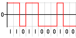
The binary signal is encoded using rectangular pulse-amplitude modulation with polar NRZ(L), or polar non-return-to-zero-level code.
In telecommunications, a non-return-to-zero (NRZ) line code is a binary code in which ones are represented by one significant condition, usually a positive voltage, while zeros are represented by some other significant condition, usually a negative voltage, with no other neutral or rest condition.
For a given data signaling rate, i.e., bit rate, the NRZ code requires only half the baseband bandwidth required by the Manchester code (the passband bandwidth is the same). The pulses in NRZ have more energy than a return-to-zero (RZ) code, which also has an additional rest state beside the conditions for ones and zeros.
When used to represent data in an asynchronous communication scheme, the absence of a neutral state requires other mechanisms for bit synchronization when a separate clock signal is not available. Since NRZ is not inherently a self-clocking signal, some additional synchronization technique must be used for avoiding bit slips; examples of such techniques are a run-length-limited constraint and a parallel synchronization signal.
Variants
NRZ can refer to any of the following serializer line codes:
Code name
Alternate name
Complete name
Description
NRZ(L)
NRZL
Non-return-to-zero level
Appears as raw binary bits without any coding. Typically binary 1 maps to logic-level high, and binary 0 maps to logic-level low. Inverse logic mapping is also a type of NRZ(L) code.
NRZ(I)
NRZI
Non-return-to-zero inverted
Refers to either an NRZ(M) or NRZ(S) code.
NRZ(M)
NRZM
Non-return-to-zero mark
Serializer mapping {0: constant, 1: toggle}.
NRZ(S)
NRZS
Non-return-to-zero space
Serializer mapping {0: toggle, 1: constant}.
NRZ(C)
NRZC
Non-return-to-zero change
The NRZ code also can be classified as a polar or non-polar, where polar refers to a mapping to voltages of +V and −V, and non-polar refers to a voltage mapping of +V and 0, for the corresponding binary values of 1 and 0.
Unipolar NRZ(L), or unipolar non-return-to-zero level
One is represented by a DC bias on the transmission line (conventionally positive), while zero is represented by the absence of bias – the line at 0 volts or grounded. For this reason it is also known as on-off keying. In clock language, a one transitions to or remains at a biased level on the trailing clock edge of the previous bit, while zero transitions to or remains at no bias on the trailing clock edge of the previous bit. Among the disadvantages of unipolar NRZ is that it allows for long series without change, which makes synchronization difficult, although this is not unique to the unipolar case. One solution is to not send bytes without transitions. More critically, and unique to unipolar NRZ, are issues related to the presence of a transmitted DC level – the power spectrum of the transmitted signal does not approach zero at zero frequency. This leads to two significant problems: first, the transmitted DC power leads to higher power losses than other encodings, and second, the presence of a DC signal component requires that the transmission line be DC-coupled.
Bipolar non-return-to-zero level
One is represented by one physical level (usually a positive voltage), while zero is represented by another level (usually a negative voltage). In clock language, in bipolar NRZ-level the voltage swings from positive to negative on the trailing edge of the previous bit clock cycle.
An example of this is RS-232, where one is −12V to −5V and zero is +5V to +12V.
Non-return-to-zero space
Non-return-to-zero spaceEncoder for NRZS, toggle on zero
One is represented by no change in physical level, while zero is represented by a change in physical level. In clock language, the level transitions on the trailing clock edge of the previous bit to represent a zero.
This change-on-zero is used by High-Level Data Link Control and USB. They both avoid long periods of no transitions (even when the data contains long sequences of 1 bits) by using zero-bit insertion. HDLC transmitters insert a 0 bit after 5 contiguous 1 bits (except when transmitting the frame delimiter 01111110). USB transmitters insert a 0 bit after 6 consecutive 1 bits. The receiver at the far end uses every transition — both from 0 bits in the data and these extra non-data 0 bits — to maintain clock synchronization. The receiver otherwise ignores these non-data 0 bits.
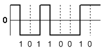
Non-return-to-zero inverted
An example of the NRZI encoding, transition on 1The opposite convention, transition on 0Encoder for NRZ-M, toggle on one
Non-return-to-zero, inverted (NRZI, also known as non-return to zero IBM,[1]inhibit code,[2] or IBM code[2]) was devised by Bryon E. Phelps (IBM) in 1956.[2][3] It is a method of mapping a binarysignal to a physical signal for transmission over some transmission medium. The two-level NRZI signal distinguishes data bits by the presence or absence of a transition at a clock boundary. The NRZI encoded signal can be decoded unambiguously after passing through a data path that doesn’t preserve polarity.
Which bit value corresponds to a transition varies in practice, NRZI applies equally to both. Magnetic storage generally uses the NRZ-M, non-return-to-zero mark convention: a logical 1 is encoded as a transition, and a logical 0 is encoded as no transition. The HDLC and Universal Serial Bus protocols use the opposite NRZ-S, non-return-to-zero space convention: a logical 0 is a transition, and a logical 1 is no transition. Neither NRZI encoding guarantees that the encoded bitstream has transitions.
An asynchronous receiver uses an independent bit clock that is phase synchronized by detecting bit transitions. When an asynchronous receiver decodes a block of bits without a transition longer than the period of the difference between the frequency of the transmitting and receiving bit clocks, the decoder’s bit clock is either 1 bit earlier than the encoder resulting in a duplicated bit being inserted in the decoded data stream, or the decoder’s bit clock is 1 bit later than the encoder resulting in a duplicated bit being removed from the decoded data stream. Both are referred to as bit slip denoting that the phase of the bit clock has slipped a bit period.
Forcing transitions at intervals shorter than the bit clock difference period allows an asynchronous receiver to be used for NRZI bit streams. Additional transitions necessarily consume some of the data channel’s rate capacity. Consuming no more of the channel capacity than necessary to maintain bit clock synchronization without increasing costs related to complexity is a problem with many possible solutions.
Run-length limited (RLL) encodings have been used for magnetic disk and tape storage devices using fixed-rate RLL codes that increase the channel data rate by a known fraction of the information data rate. HDLC and USB use bit stuffing: inserting an additional 0 bit before NRZ-S encoding to force a transition in the encoded data sequence after 5 (HDLC) or 6 (USB) consecutive 1 bits. Bit stuffing consumes channel capacity only when necessary but results in a variable information data rate.
Synchronized non-return-to-zero
Synchronized NRZI (SNRZI) and group-coded recording (GCR) are modified forms of NRZI.[4] In SNRZI-M each 8-bit group is extended to 9 bits by a 1 in order to insert a transition for synchronisation.[4]
Comparison with return-to-zero
Return-to-zero describes a line code used in telecommunications in which the signal drops (returns) to zero between each pulse. This takes place even if a number of consecutive 0s or 1s occur in the signal. The signal is self-clocking. This means that a separate clock does not need to be sent alongside the signal, but suffers from using twice the bandwidth to achieve the same data-rate as compared to non-return-to-zero format.
Although return-to-zero contains a provision for synchronization, it still may have a DC component resulting in baseline wander during long strings of 0 or 1 bits, just like the line code non-return-to-zero.
123Palmer, Dean (2005). "Section 1: Recording Systems, 1: A brief history of magnetic recording". In Vasic, Bane; Kurtas, Erozan M. (eds.). Coding and Signal Processing for Magnetic Recording Systems (1sted.). CRC Press. pp.I-6, I-15. ISBN0-8493-1524-7.
↑US 2774646,Phelps, Bryon E.,"Magnetic recording method",published 1956-12-18, assigned to IBM (See also: DE950858C)
12Patel, Arvind Motibhai (1988). "5. Signal and Error-Control Coding". In Mee, C. Denis; Daniel, Eric D. (eds.). Magnetic Recording. Vol.II: Computer Data Storage (1sted.). McGraw-Hill Book Company. ISBN0-07-041272-3.
This page is based on this Wikipedia article Text is available under the CC BY-SA 4.0 license; additional terms may apply. Images, videos and audio are available under their respective licenses.