Transmission medium

Last updated
Cutaway diagram of Coaxial cable, one example of a transmission medium Coaxial cable cutaway.svg
Cutaway diagram of Coaxial cable, one example of a transmission medium

A transmission medium is a system or substance that can mediate the propagation of signals for the purposes of telecommunication. Signals are typically imposed on a wave of some kind suitable for the chosen medium. For example, data can modulate sound, and a transmission medium for sounds may be air, but solids and liquids may also act as the transmission medium. Vacuum or air constitutes a good transmission medium for electromagnetic waves such as light and radio waves. While a material substance is not required for electromagnetic waves to propagate, such waves are usually affected by the transmission media they pass through, for instance, by absorption or reflection or refraction at the interfaces between media. Technical devices can therefore be employed to transmit or guide waves. Thus, an optical fiber or a copper cable is used as transmission media.

Contents

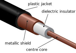
Electromagnetic radiation can be transmitted through an optical medium, such as optical fiber, or through twisted pair wires, coaxial cable, or dielectric-slab waveguides. It may also pass through any physical material that is transparent to the specific wavelength, such as water, air, glass, or concrete. Sound is, by definition, the vibration of matter, so it requires a physical medium for transmission, as do other kinds of mechanical waves and heat energy. Historically, science incorporated various aether theories to explain the transmission medium. However, it is now known that electromagnetic waves do not require a physical transmission medium, and so can travel through the vacuum of free space. Regions of the insulative vacuum can become conductive for electrical conduction through the presence of free electrons, holes, or ions.

Optical medium

In optics, an optical medium is material through which light and other electromagnetic waves propagate. It is a form of transmission medium. The permittivity and permeability of the medium define how electromagnetic waves propagate in it.

Telecommunications

A physical medium in data communications is the transmission path over which a signal propagates. Many different types of transmission media are used as communications channel.

In many cases, communication is in the form of electromagnetic waves. With guided transmission media, the waves are guided along a physical path; examples of guided media include phone lines, twisted pair cables, coaxial cables, and optical fibers. Unguided transmission media are methods that allow the transmission of data without the use of physical means to define the path it takes. Examples of this include microwave, radio or infrared. Unguided media provide a means for transmitting electromagnetic waves but do not guide them; examples are propagation through air, vacuum and seawater.

The term direct link is used to refer to the transmission path between two devices in which signals propagate directly from transmitters to receivers with no intermediate devices, other than amplifiers or repeaters used to increase signal strength. This term can apply to both guided and unguided media.

Simplex versus duplex

A signal transmission may be simplex, half-duplex, or full-duplex.

In simplex transmission, signals are transmitted in only one direction; one station is a transmitter and the other is the receiver. In the half-duplex operation, both stations may transmit, but only one at a time. In full-duplex operation, both stations may transmit simultaneously. In the latter case, the medium is carrying signals in both directions at the same time.

Types

In general, a transmission medium can be classified as

There are two main types of transmission media:

One of the most common physical media used in networking is copper wire. Copper wire to carry signals to long distances using relatively low amounts of power. The unshielded twisted pair (UTP) is eight strands of copper wire, organized into four pairs. [1]

Guided media

Twisted pair

Twisted pair cabling is a type of wiring in which two conductors of a single circuit are twisted together for the purposes of improving electromagnetic compatibility. Compared to a single conductor or an untwisted balanced pair, a twisted pair reduces electromagnetic radiation from the pair and crosstalk between neighboring pairs and improves rejection of external electromagnetic interference. It was invented by Alexander Graham Bell. [2]

Coaxial cable

RG-59 flexible coaxial cable composed of:
Outer plastic sheath
Woven copper shield
Inner dielectric insulator
Copper core RG-59.jpg
RG-59 flexible coaxial cable composed of:
  1. Outer plastic sheath
  2. Woven copper shield
  3. Inner dielectric insulator
  4. Copper core

Coaxial cable, or coax (pronounced /ˈk.æks/ ) is a type of electrical cable that has an inner conductor surrounded by a tubular insulating layer, surrounded by a tubular conducting shield. Many coaxial cables also have an insulating outer sheath or jacket. The term coaxial comes from the inner conductor and the outer shield sharing a geometric axis. Coaxial cable was invented by English physicist, engineer, and mathematician Oliver Heaviside, who patented the design in 1880. [3]

Coaxial cable is a type of transmission line, used to carry high frequency electrical signals with low losses. It is used in such applications as telephone trunk lines, broadband internet networking cables, high-speed computer data busses, carrying cable television signals, and connecting radio transmitters and receivers to their antennas. It differs from other shielded cables because the dimensions of the cable and connectors are controlled to give a precise, constant conductor spacing, which is needed for it to function efficiently as a transmission line.

Optical fiber

A bundle of optical fiber Fibreoptic.jpg
A bundle of optical fiber
Fiber crew installing a 432-count fiber cable underneath the streets of Midtown Manhattan, New York City Stealth Fiber Crew installing fiber cable underneath the streets of Manhattan.jpg
Fiber crew installing a 432-count fiber cable underneath the streets of Midtown Manhattan, New York City
A TOSLINK fiber optic audio cable with red light being shone in one end transmits the light to the other end Fiber optic illuminated.jpg
A TOSLINK fiber optic audio cable with red light being shone in one end transmits the light to the other end
A wall-mount cabinet containing optical fiber interconnects. The yellow cables are single mode fibers; the orange and aqua cables are multi-mode fibers: 50/125 um OM2 and 50/125 um OM3 fibers respectively. Optical-fibre-junction-box.jpg
A wall-mount cabinet containing optical fiber interconnects. The yellow cables are single mode fibers; the orange and aqua cables are multi-mode fibers: 50/125 µm OM2 and 50/125 µm OM3 fibers respectively.

Optical fiber, which has emerged as the most commonly used transmission medium for long-distance communications, is a thin strand of glass that guides light along its length. Four major factors favor optical fiber over copper: data rates, distance, installation, and costs. Optical fiber can carry huge amounts of data compared to copper. It can be run for hundreds of miles without the need for signal repeaters, in turn, reducing maintenance costs and improving the reliability of the communication system because repeaters are a common source of network failures. Glass is lighter than copper allowing for less need for specialized heavy-lifting equipment when installing long-distance optical fiber. Optical fiber for indoor applications cost approximately a dollar a foot, the same as copper. [4]

Multimode and single mode are two types of commonly used optical fiber. Multimode fiber uses LEDs as the light source and can carry signals over shorter distances, about 2 kilometers. Single mode can carry signals over distances of tens of miles.

An optical fiber is a flexible, transparent fiber made by drawing glass (silica) or plastic to a diameter slightly thicker than that of a human hair. [5] Optical fibers are used most often as a means to transmit light between the two ends of the fiber and find wide usage in fiber-optic communications, where they permit transmission over longer distances and at higher bandwidths (data rates) than electrical cables. Fibers are used instead of metal wires because signals travel along them with less loss; in addition, fibers are immune to electromagnetic interference, a problem from which metal wires suffer excessively. [6] Fibers are also used for illumination and imaging, and are often wrapped in bundles so they may be used to carry light into, or images out of confined spaces, as in the case of a fiberscope. [7] Specially designed fibers are also used for a variety of other applications, some of them being fiber optic sensors and fiber lasers. [8]

Optical fibers typically include a core surrounded by a transparent cladding material with a lower index of refraction. Light is kept in the core by the phenomenon of total internal reflection which causes the fiber to act as a waveguide. [9] Fibers that support many propagation paths or transverse modes are called multi-mode fibers, while those that support a single mode are called single-mode fibers (SMF). Multi-mode fibers generally have a wider core diameter [10] and are used for short-distance communication links and for applications where high power must be transmitted.[ citation needed ] Single-mode fibers are used for most communication links longer than 1,000 meters (3,300 ft).[ citation needed ]

Being able to join optical fibers with low loss is important in fiber optic communication. [11] This is more complex than joining electrical wire or cable and involves careful cleaving of the fibers, precise alignment of the fiber cores, and the coupling of these aligned cores. For applications that demand a permanent connection a fusion splice is common. In this technique, an electric arc is used to melt the ends of the fibers together. Another common technique is a mechanical splice, where the ends of the fibers are held in contact by mechanical force. Temporary or semi-permanent connections are made by means of specialized optical fiber connectors. [12]

The field of applied science and engineering concerned with the design and application of optical fibers is known as fiber optics. The term was coined by Indian physicist Narinder Singh Kapany, who is widely acknowledged as the father of fiber optics. [13]

Unguided media

Radio

Radio propagation is the behavior of radio waves as they travel, or are propagated, from one point to another, or into various parts of the atmosphere. [14] As a form of electromagnetic radiation, like light waves, radio waves are affected by the phenomena of reflection, refraction, diffraction, absorption, polarization, and scattering. [15] Understanding the effects of varying conditions on radio propagation has many practical applications, from choosing frequencies for international shortwave broadcasters, to designing reliable mobile telephone systems, to radio navigation, to operation of radar systems.

Different types of propagation are used in practical radio transmission systems. Line-of-sight propagation means radio waves that travel in a straight line from the transmitting antenna to the receiving antenna. Line of sight transmission is used to medium-range radio transmission such as cell phones, cordless phones, walkie-talkies, wireless networks, FM radio and television broadcasting and radar, and satellite communication, such as satellite television. Line-of-sight transmission on the surface of the Earth is limited to the distance to the visual horizon, which depends on the height of transmitting and receiving antennas. It is the only propagation method possible at microwave frequencies and above. At microwave frequencies, moisture in the atmosphere (rain fade) can degrade transmission.

At lower frequencies in the MF, LF, and VLF bands, due to diffraction radio waves can bend over obstacles like hills, and travel beyond the horizon as surface waves which follow the contour of the Earth. These are called ground waves. AM broadcasting stations use ground waves to cover their listening areas. As the frequency gets lower, the attenuation with distance decreases, so very low frequency (VLF) and extremely low frequency (ELF) ground waves can be used to communicate worldwide. VLF and ELF waves can penetrate significant distances through water and earth, and these frequencies are used for mine communication and military communication with submerged submarines.

At medium wave and shortwave frequencies (MF and HF bands) radio waves can refract from a layer of charged particles (ions) high in the atmosphere, called the ionosphere. This means that radio waves transmitted at an angle into the sky can be reflected back to Earth beyond the horizon, at great distances, even transcontinental distances. This is called skywave propagation. It is used by amateur radio operators to talk to other countries and shortwave broadcasting stations that broadcast internationally. Skywave communication is variable, dependent on conditions in the upper atmosphere; it is most reliable at night and in the winter. Due to its unreliability, since the advent of communication satellites in the 1960s, many long-range communication that previously used skywaves now use satellites.

In addition, there are several less common radio propagation mechanisms, such as tropospheric scattering (troposcatter) and near vertical incidence skywave (NVIS) which are used in specialized communication systems.

Digital encoding

Transmission and reception of data is typically performed in four steps: [16]

  1. At the transmitting end, the data is encoded to a binary representation.
  2. A carrier signal is modulated as specified by the binary representation.
  3. At the receiving end, the carrier signal is demodulated into a binary representation.
  4. The data is decoded from the binary representation.

See also

Related Research Articles

In physics, attenuation is the gradual loss of flux intensity through a medium. For instance, dark glasses attenuate sunlight, lead attenuates X-rays, and water and air attenuate both light and sound at variable attenuation rates.

A communications system or communication system is a collection of individual telecommunications networks systems, relay stations, tributary stations, and terminal equipment usually capable of interconnection and interoperation to form an integrated whole. The components of a communications system serve a common purpose, are technically compatible, use common procedures, respond to controls, and operate in union.

<span class="mw-page-title-main">Multiplexing</span> Method of combining multiple signals into one signal over a shared medium

In telecommunications and computer networking, multiplexing is a method by which multiple analog or digital signals are combined into one signal over a shared medium. The aim is to share a scarce resource – a physical transmission medium. For example, in telecommunications, several telephone calls may be carried using one wire. Multiplexing originated in telegraphy in the 1870s, and is now widely applied in communications. In telephony, George Owen Squier is credited with the development of telephone carrier multiplexing in 1910.

<span class="mw-page-title-main">Network topology</span> Arrangement of the elements of a communication network

Network topology is the arrangement of the elements of a communication network. Network topology can be used to define or describe the arrangement of various types of telecommunication networks, including command and control radio networks, industrial fieldbusses and computer networks.

<span class="mw-page-title-main">Waveguide</span> Structure that guides waves efficiently

A waveguide is a structure that guides waves by restricting the transmission of energy to one direction. Common types of waveguides include acoustic waveguides which direct sound, optical waveguides which direct light, and radio-frequency waveguides which direct electromagnetic waves other than light like radio waves.

<span class="mw-page-title-main">Frequency-division multiplexing</span> Signal processing technique in telecommunications

In telecommunications, frequency-division multiplexing (FDM) is a technique by which the total bandwidth available in a communication medium is divided into a series of non-overlapping frequency bands, each of which is used to carry a separate signal. This allows a single transmission medium such as a microwave radio link, cable or optical fiber to be shared by multiple independent signals. Another use is to carry separate serial bits or segments of a higher rate signal in parallel.

<span class="mw-page-title-main">Communication channel</span> Physical or logical connection used for transmission of information

A communication channel refers either to a physical transmission medium such as a wire, or to a logical connection over a multiplexed medium such as a radio channel in telecommunications and computer networking. A channel is used for information transfer of, for example, a digital bit stream, from one or several senders to one or several receivers. A channel has a certain capacity for transmitting information, often measured by its bandwidth in Hz or its data rate in bits per second.

<span class="mw-page-title-main">Medium frequency</span> The range 300-3000 kHz of the electromagnetic spectrum

Medium frequency (MF) is the ITU designation for radio frequencies (RF) in the range of 300 kilohertz (kHz) to 3 megahertz (MHz). Part of this band is the medium wave (MW) AM broadcast band. The MF band is also known as the hectometer band as the wavelengths range from ten to one hectometers. Frequencies immediately below MF are denoted as low frequency (LF), while the first band of higher frequencies is known as high frequency (HF). MF is mostly used for AM radio broadcasting, navigational radio beacons, maritime ship-to-shore communication, and transoceanic air traffic control.

<span class="mw-page-title-main">High frequency</span> The range 3-30 MHz of the electromagnetic spectrum

High frequency (HF) is the ITU designation for the range of radio frequency electromagnetic waves between 3 and 30 megahertz (MHz). It is also known as the decameter band or decameter wave as its wavelengths range from one to ten decameters. Frequencies immediately below HF are denoted medium frequency (MF), while the next band of higher frequencies is known as the very high frequency (VHF) band. The HF band is a major part of the shortwave band of frequencies, so communication at these frequencies is often called shortwave radio. Because radio waves in this band can be reflected back to Earth by the ionosphere layer in the atmosphere – a method known as "skip" or "skywave" propagation – these frequencies are suitable for long-distance communication across intercontinental distances and for mountainous terrains which prevent line-of-sight communications. The band is used by international shortwave broadcasting stations (3.95–25.82 MHz), aviation communication, government time stations, weather stations, amateur radio and citizens band services, among other uses.

Radio propagation is the behavior of radio waves as they travel, or are propagated, from one point to another in vacuum, or into various parts of the atmosphere. As a form of electromagnetic radiation, like light waves, radio waves are affected by the phenomena of reflection, refraction, diffraction, absorption, polarization, and scattering. Understanding the effects of varying conditions on radio propagation has many practical applications, from choosing frequencies for amateur radio communications, international shortwave broadcasters, to designing reliable mobile telephone systems, to radio navigation, to operation of radar systems.

<span class="mw-page-title-main">Skywave</span> Propagation of radio waves beyond the radio horizon.

In radio communication, skywave or skip refers to the propagation of radio waves reflected or refracted back toward Earth from the ionosphere, an electrically charged layer of the upper atmosphere. Since it is not limited by the curvature of the Earth, skywave propagation can be used to communicate beyond the horizon, at intercontinental distances. It is mostly used in the shortwave frequency bands.

A link budget is an accounting of all of the power gains and losses that a communication signal experiences in a telecommunication system; from a transmitter, through a communication medium such as radio waves, cable, waveguide, or optical fiber, to the receiver. It is an equation giving the received power from the transmitter power, after the attenuation of the transmitted signal due to propagation, as well as the antenna gains and feedline and other losses, and amplification of the signal in the receiver or any repeaters it passes through. A link budget is a design aid, calculated during the design of a communication system to determine the received power, to ensure that the information is received intelligibly with an adequate signal-to-noise ratio. Randomly varying channel gains such as fading are taken into account by adding some margin depending on the anticipated severity of its effects. The amount of margin required can be reduced by the use of mitigating techniques such as antenna diversity or multiple-input and multiple-output (MIMO).

<span class="mw-page-title-main">Optical fiber</span> Light-conducting fiber

An optical fiber, or optical fibre, is a flexible glass or plastic fiber that can transmit light from one end to the other. Such fibers find wide usage in fiber-optic communications, where they permit transmission over longer distances and at higher bandwidths than electrical cables. Fibers are used instead of metal wires because signals travel along them with less loss and are immune to electromagnetic interference. Fibers are also used for illumination and imaging, and are often wrapped in bundles so they may be used to carry light into, or images out of confined spaces, as in the case of a fiberscope. Specially designed fibers are also used for a variety of other applications, such as fiber optic sensors and fiber lasers.

Optical networking is a means of communication that uses signals encoded in light to transmit information in various types of telecommunications networks. These include limited range local-area networks (LAN) or wide area networks (WANs), which cross metropolitan and regional areas as well as long-distance national, international and transoceanic networks. It is a form of optical communication that relies on optical amplifiers, lasers or LEDs and wavelength-division multiplexing (WDM) to transmit large quantities of data, generally across fiber-optic cables. Because it is capable of achieving extremely high bandwidth, it is an enabling technology for the Internet and telecommunication networks that transmit the vast majority of all human and machine-to-machine information.

<span class="mw-page-title-main">Waveguide (radio frequency)</span> Hollow metal pipe used to carry radio waves

In radio-frequency engineering and communications engineering, waveguide is a hollow metal pipe used to carry radio waves. This type of waveguide is used as a transmission line mostly at microwave frequencies, for such purposes as connecting microwave transmitters and receivers to their antennas, in equipment such as microwave ovens, radar sets, satellite communications, and microwave radio links.

<span class="mw-page-title-main">Fiber-optic communication</span> Transmitting information over optical fiber

Fiber-optic communication is a method of transmitting information from one place to another by sending pulses of infrared or visible light through an optical fiber. The light is a form of carrier wave that is modulated to carry information. Fiber is preferred over electrical cabling when high bandwidth, long distance, or immunity to electromagnetic interference is required. This type of communication can transmit voice, video, and telemetry through local area networks or across long distances.

<span class="mw-page-title-main">Telecommunications engineering</span> Engineering science that deals with the recording, transmission, processing and storage of messages

Telecommunications engineering is a subfield of electronics engineering which seeks to design and devise systems of communication at a distance. The work ranges from basic circuit design to strategic mass developments. A telecommunication engineer is responsible for designing and overseeing the installation of telecommunications equipment and facilities, such as complex electronic switching systems, and other plain old telephone service facilities, optical fiber cabling, IP networks, and microwave transmission systems. Telecommunications engineering also overlaps with broadcast engineering.

Telecommunications cable is a type of guided transmission medium. Telecommunications are based on transmitting and receiving modulated waves/signals through a medium. Types of telecommunications cable include: electrical cables when electric current is carried; transmission lines and waveguides when electromagnetic waves are transmitted; optical fibers when light signals are transmitted.

Networking cable is a piece of networking hardware used to connect one network device to other network devices or to connect two or more computers to share devices such as printers or scanners. Different types of network cables, such as coaxial cable, optical fiber cable, and twisted pair cables, are used depending on the network's topology, protocol, and size. The devices can be separated by a few meters or nearly unlimited distances.

Physical media refers to the physical materials that are used to store or transmit information in data communications. These physical media are generally physical objects made of materials such as copper or glass. They can be touched and felt, and have physical properties such as weight and color. For a number of years, copper and glass were the only media used in computer networking.

References

  1. Agrawal, Manish (2010). Business Data Communications. John Wiley & Sons, Inc. p. 37. ISBN   978-0470483367.
  2. McBee, Jim; Barnett, David; Groth, David (2004). Cabling : the complete guide to network wiring (3rd ed.). San Francisco: SYBEX. p. 11. ISBN   9780782143317.
  3. Nahin, Paul J. (2002). Oliver Heaviside: The Life, Work, and Times of an Electrical Genius of the Victorian Age. ISBN   0-8018-6909-9.
  4. Agrawal, Manish (2010). Business Data Communications. John Wiley & Sons, Inc. pp. 41–43. ISBN   978-0470483367.
  5. "Optical Fiber". www.thefoa.org. The Fiber Optic Association. Archived from the original on 24 January 2009. Retrieved 17 April 2015.
  6. Senior, John M.; Jamro, M. Yousif (2009). Optical fiber communications: principles and practice. Pearson Education. pp. 7–9. ISBN   978-0130326812.
  7. "Birth of Fiberscopes". www.olympus-global.com. Olympus Corporation. Archived from the original on 9 May 2015. Retrieved 17 April 2015.
  8. Lee, Byoungho (2003). "Review of the present status of optical fiber sensors". Optical Fiber Technology. 9 (2): 57–79. Bibcode:2003OptFT...9...57L. doi:10.1016/s1068-5200(02)00527-8.
  9. Senior, pp. 12–14
  10. The Optical Industry & Systems Purchasing Directory. Optical Publishing Company. 1984.
  11. Senior, p. 218
  12. Senior, pp. 234–235
  13. "Narinder Singh Kapany Chair in Opto-electronics". ucsc.edu. Archived from the original on 2017-05-21. Retrieved 2019-05-06.
  14. H. P. Westman et al., (ed), Reference Data for Radio Engineers, Fifth Edition, 1968, Howard W. Sams and Co., ISBN   0-672-20678-1, Library of Congress Card No. 43-14665 page 26-1
  15. Demetrius T Paris and F. Kenneth Hurd, Basic Electromagnetic Theory, McGraw Hill, New York 1969 ISBN   0-07-048470-8, Chapter 8
  16. Agrawal, Manish (2010). Business Data Communications. John Wiley & Sons, Inc. p. 54. ISBN   978-0470483367.